3 Conditions of Acceptability
YASKAWA ELECTRIC TOBP C710606 21D YASKAWA AC Drive - V1000 Finless Installation Guide 11
Table 2 Recommended Heatsink Plate Thermal Compounds
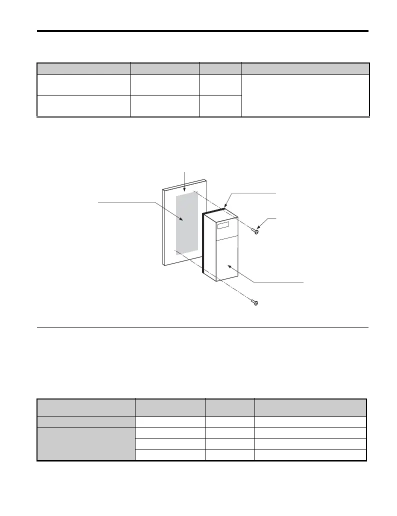
When applying the thermal compound, spread it over the surface of the heatsink plate. After
mounting the heatsink plate to the metal back panel, wipe away any excess compound from
around the heatsink plate.
Figure 3
Figure 4 Application of Thermal Compound
◆ Drive Heatsink Plate Installation Screw Size and Tightening
Torque
Screw size and torque specifications for heatsink plate installation screws that hold the drive
to a metal back panel are listed in Tab le 3.
Table 3 Screw Size and Tightening Torque
Manufacturer Type Model Recommended spread amount
Shin-Etsu Chemical Inc.
Oil-based
compound
G746
100 μm
Apply the coating evenly across the
surface
Dow Corning Toray Inc.
Silicone compound
for heat dissipation
SC4471CV
Voltage Class
Model
CIMR-V
Screw Size
Tightening Torque
Nxm (ft-lbf)
Single-Phase 200 V class BA0001 ~ BA0012 M4 1.0 to 1.3 (0.74 to 0.96)
Three-phase 200V class
2A0001 ~ 2A0020 M4 1.0 to 1.3 (0.74 to 0.96)
2A0030 ~ 2A0056 M5 2.0 to 2.5 (1.48 to 1.84)
2A0069 M6 4.0 to 5.0 (2.95 to 3.69)
Metal panel
Thermal compound
Heatsink plate
Installation
screws
V1000 Finless

 Loading...


