22 YASKAWA ELECTRIC TOBP C710606 21D YASKAWA AC Drive - V1000 Finless Installation Guide
6 Selecting an External Heatsink
6 Selecting an External Heatsink
This section describes the selection of a suitable external heatsink when using a V1000
Finless drive.
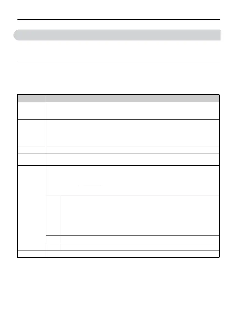
◆ Data Required for Heatsink Selection
The table below shows data that are needed to select a heatsink that suits drive and
application.
Symbol Description
P
Loss
Drive heat loss
Refer to V1000 Finless Drive Watt Loss Thermal Characteristics on page 14
to check
the amount of heat loss from the heatsink plate of the drive.
T
HSP_max
Maximum heatsink plate temperature
This is the temperature at the surface of the heatsink plate. It can be monitored with U4-08. The
maximum allowable value depends on drive model.
CIMR-VBA, CIMR-V2A0001~0020, CIMR-V4A0001~0011: 90°C
CIMR-V2A0030~0069, CIMR-V4A0018~0038: 80°C
T
Amb
External heatsink ambient temperature (air temperature around heatsink)
Rθ
HSP
Heatsink plate thermal resistance
This value is 0.05 K/W
Rθ
HSP-EHS
Thermal resistance between the heatsink plate and the external heatsink
Can be calculated by
A
th
Heat transfer area between drive heatsink plate and external heatsink
Note: Due to uneven heat generation across the heatsink plate (by arrangement
of internal components) the effective area for heat transfer is only ~70% of
heatsink plate area. This must be considered when calculating the thermal
resistance.
Refer to Dimensions on page 17 for values of H and W to calculate the area of
the heatsink plate.
λ
Comp
Thermal conductivity of the heatsink thermal compound
d
Comp
Thickness of the thermal compound
Rθ
EHS
Thermal resistance of the external heatsink
Rθ
HSP-EHS
=
d
Comp
λ
comp
A
th

 Loading...


