(2) Closed-Loop Connectors Size
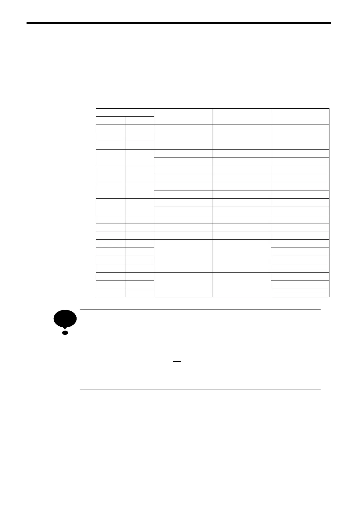
Table 10 Closed Loop Connectors Sizes (JIS C 2805) (For 200 V/400 V classes)
Wire Size
mm
2
AWG
Terminal Screw Tightening Torque (N•m) Closed Loop Connectors
0.5 20
0.75 18
M3.5
0.8 to 1.0
1.25 to 3.5
1.25 16
.
o
.
.
o
M4 1.2 to 1.4 2to4
2 14
M5 2.1 to 2.5 2to5
M4 1.2 to 1.4 3.5 to 4
3.5 12
M5 2.1 to 2.5 3.5 to 5
M4 1.2 to 1.4 5.5 to 4
5.5 10
M5 2.1 to 2.5 5.5 to 5
M5 2.1 to 2.5 8to5
8 8
M6 3.6 to 5.1 8to6
14 6 M6 3.6 to 5.1 14 to 6
22 4 M8 8.2 to 10.2 22 to 8
30/38 3/2 M8 8.2 to 10.2 38 to 8
30/38 3/2 38 to 10
50/60 1/1/0
60 to 10
80 3/0
M10 18 to 23
80 to 10
100 4/0 100 to 10
100 4/0 100 to 12
150 300
M12 31.5 to
39.5
150 to 12
200 400 200 to 12
Determine the wire size for the main circuit so that line voltage drop is within
2 % of the rated voltage. Line voltage drop is calculated as follows:
(If there is a possibility of excessive voltage drop, use a larger wire suitable to
the required length.)
Line voltage drop (V) =
3
p
× wire resistance (Ω/km) × wire length (m) ×cur-
rent (A) × 10
-3
NOTE
32