3.4 EXTERNAL TERMINALS
(1) Main Circuit Terminal Functions
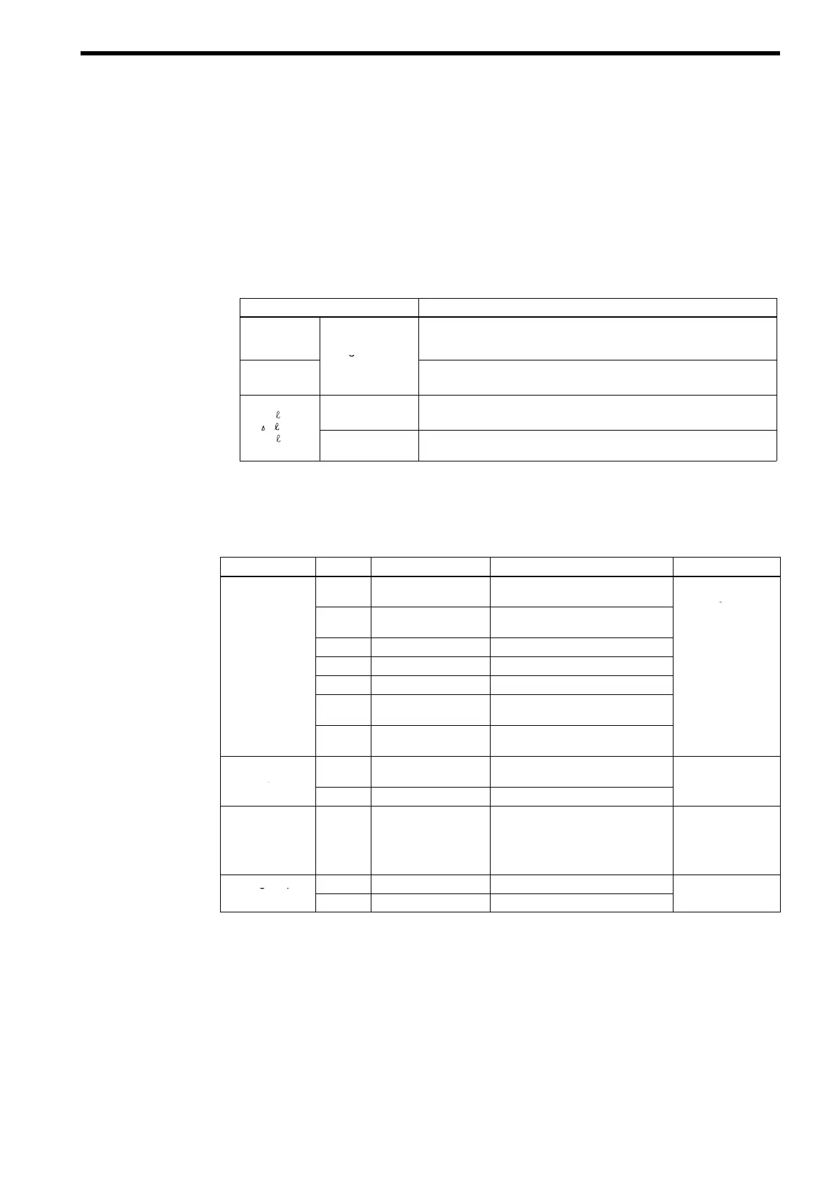
Table 11 Main Circuit Terminal Functions
Terminal Symbol Description
R/L1
S/L2
T/L3
Power
Regenerative
Main circuit AC power supply terminal for the power regenerative unit.
¨ , ©
Unit
Main Circuit Input
Connect to the Inverter’s DC power supply voltage input terminals.
S Two terminals are provided for both
¨ and ©.
r1/ 11
Power Supply
Voltage Detection
Detects the phase sequence and the voltage level.
S Connect to the power side of the power coordinating reactor.
t1/ 31
Power Input for
FAN and MC
Supplies power for the cooling fan and inrush prevention MC of the power
regenerative unit.
(2) Control Circuit Terminal Functions
Table 12 Control Circuit Terminal Functions
Type No.* Signal Input Function Signal Level
Sequence Input
S1
MANUAL RUN Run when CLOSED, stops when
OPEN
24 VDC 8 mA
Photocoupler
S2
AUTO RUN Auto run (regenerative operation)
when CLOSED
isolation
S3
EXFLT External fault when CLOSED
S4
RESET Fault reset when CLOSED
SC
Sequence Common
SS
Photocoupler internal
common
SP
Sequence +24V Power
Supply
Photocoupler
Output
M1 - M2
CONV READY Closed when power regenerative unit
is READY
48 VDC 80 mA
or less
M3 - M4
RUN CLOSE during run
Relay Output MA - MC
MB - MC
FAULT Output
(Transfer Contact)
Outputs when a fault is detected.
Terminal MA-MC : Closed during
fault detection
Terminal MB-MC : Open during
fault detection
250 VAC 1 A or less
30 VDC 1 A or less
Analog Output
AM
Input Current 5 V : 100 % of rated input current
− 10 V to + 10 VDC
AC
Analog grand
2 mA or less
* Indicates the terminal number of the control card.
3 WIRING
33