7 SPECIFICATIONS
47
7 SPECIFICATIONS
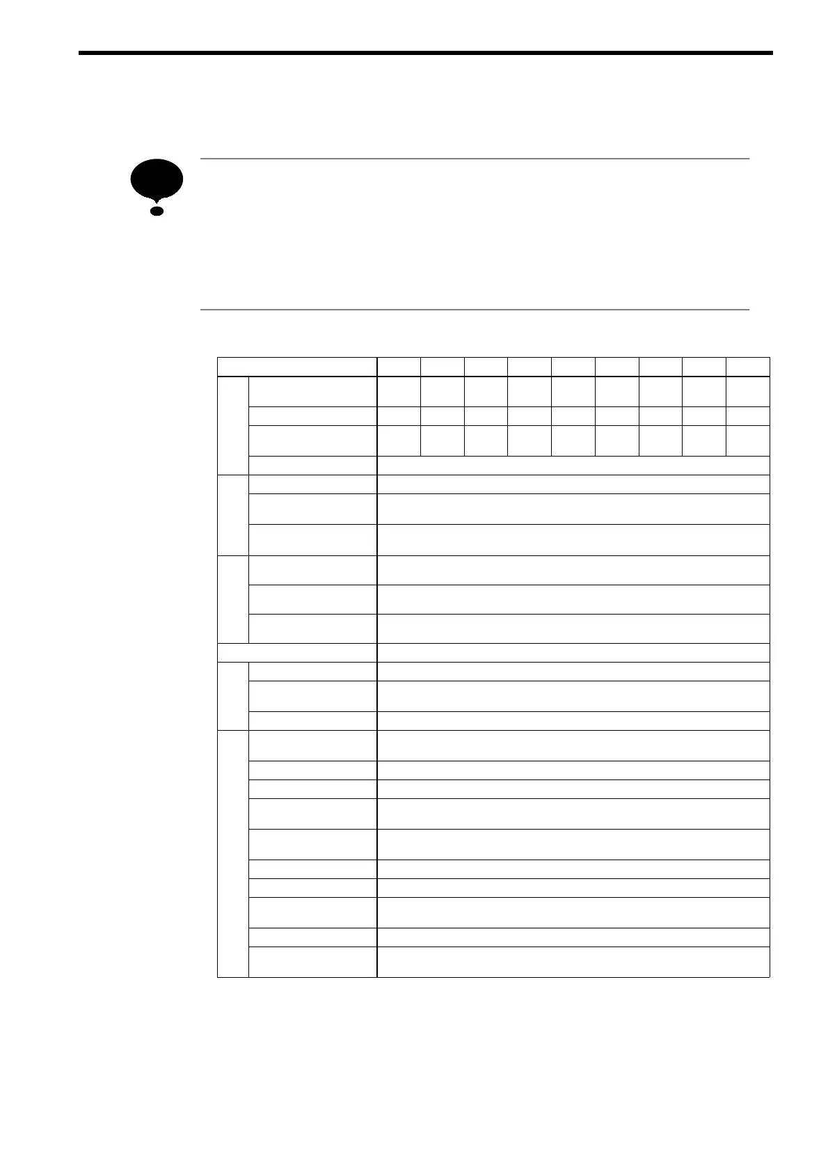
1. Use 1:1 with an inverter. Do not connect more than one inverter to one power
regenerative unit.
2. Use the power regenerative unit whose capacity is equal to one exceeding
the inverter capacity to be combined.
3. Do not use this unit with single-phase power. Use three-phase power.
Table 17 200 V Class Specifications
Model CIMR-R5Uj 23P7 25P5 27P5 2011 2015 2018 2022 2030 2037
Rated Capacity
kW
3.7 5.5 7.5 11 15 18.5 22 30 37
ting
Rated DC Current A
13 19 26 37 51 64 77 102 126
R
Rated Current on
Power Side A
10 15 20 30 40 50 60 80 100
Regenerative Torque
100 % for 1 minute, 25 % ED, 80 % continuous
r
Voltage Frequency
200 to 220 VAC 50 Hz, 200 to 230 VAC 60 Hz
t Powe
ply
Allowable Voltage
Fluctuation
+10 to −15 % (Imbalance rate between phases: within 2 %)
Input
Sup
Allowable Frequency
Fluctuation
¦3 Hz (Free phase rotation)
tics
Control Method
120° current conduction
rol
acteris
Input Power Factor
0.9 or more (Rated current)
Contr
Char
Overload Capacity
Stops in 30 seconds at approx. 150 % of rated current.
Operation Input
External terminals
Fault
1C contact output
tatus
utput
Running, READY
Signal
Photocoupler output
S
O
Analog Output
Analog output: 1 point can be selected (current monitor)
Instantaneous
Overcurrent
Stops at approx. 200 % of the current on power side
Blown Fuse
Motor stops by blown fuse.
Overload
Stops after 30 seconds at 150 % of rated current
tion
Undervoltage
(DC Voltage)
Stops at approx. 190 VDC or less.
e Func
Undervoltage
(Power Side Voltage)
Stops at approx. 150 VAC or less.
ctiv
Overload
Stops at approx. 400 VDC or more.
rote
Fin Overheat
Protected by thermister
P
Power Supply Open
Phase
Stops at power supply open phase detection.
Power Frequency Error
Stops by fluctuation more than ± 3 Hz of rated input frequency.
Power Charge
Indication
Indicated until main output voltage is approx. 50 V or less.
NOTE