APPENDIX 3 CONSTANTS LIST
61
APPENDIX 3 CONSTANTS LIST
Table A-6 shows the items that can be monitored in operation mode. The output sig-
nal levels for multi-function analog outputs shown in the table are for a gain of 100.0
and a bias of 0.00.
Table A-6 Constants Monitored in Operation Mode
Func-
tion
Con-
stant
No.
Name Function
Output Signal Level for
Multi-function
Analog Outputs
Min.
Unit
DC bus voltage
Monitors the DC volta
e of the
ower re
enerative unit’s
200 V class : 400 V/10 V
U1-02
DC Bus Voltage
internal main circuit
400 V class : 800 V/10 V
(0 to +10 V Output)
1V
AC power supply voltage
200 V class : 200 V/5 V
U1-04
AC Voltage
Monitors the AC power supply voltage.
400 V class : 400 V/5 V
(0 to +10 V Output)
1V
Current at power side
Rated current /10 V
U1-05
AC Current
Monitors the AC current at power side.
(0 to +10 V Output)
1A
Power at power side
Rated
ower /10 V
U1-07
AC Power
Monitors the AC power supply at power side.
(0 to +10 V Output)
1kW
U1-08
AC power supply
frequency
Monitors the AC
ower su
l
fre
uenc
.
60 Hz /10 V
0.01
-
AC Frequency
.
(0 to +10 V Output) Hz
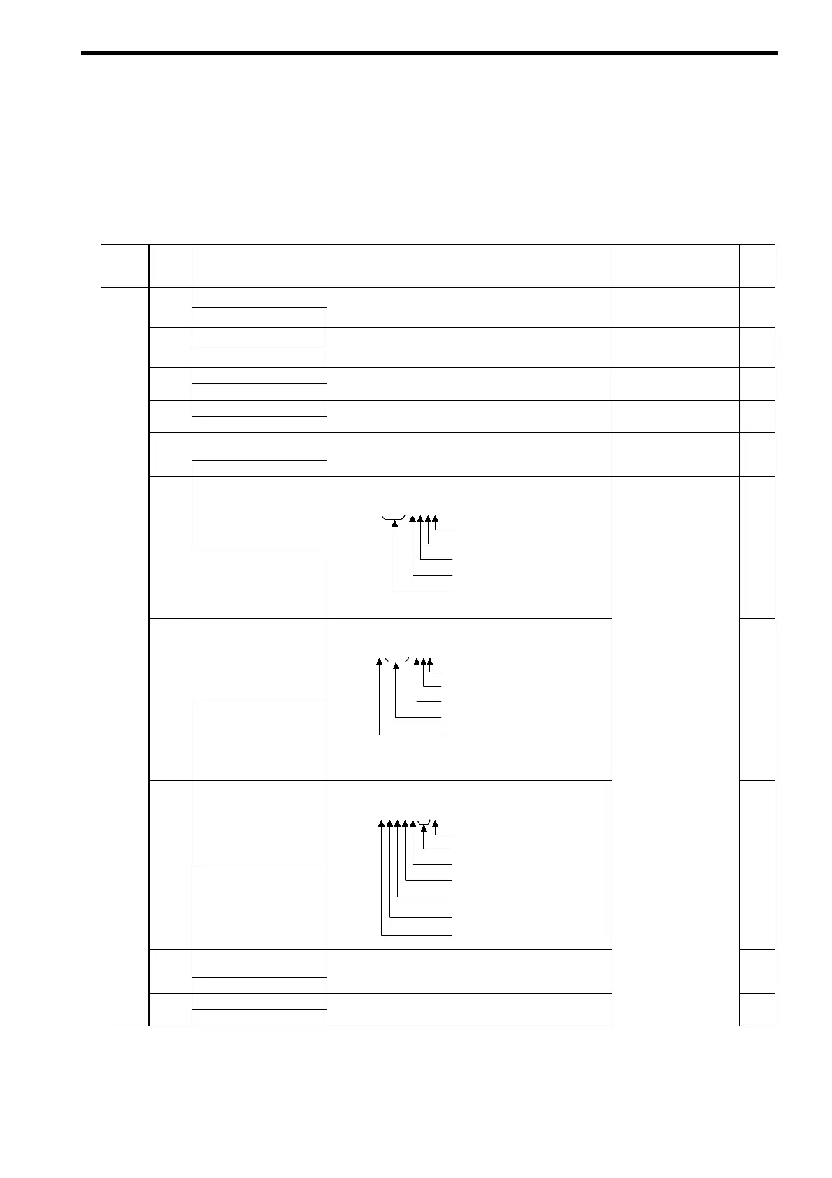
Input terminal status
Shows input ON/OFF status.
U1-10 =
00000000
1 : MANUAL RUN (terminal S1) ON
1 : AUTO RUN
terminal S2
ON
U1-10
Input Term Sts
1 : EXFLT (terminal S3) ON *1
1 : RESET (terminal S4) ON *1
1 : Not used. (always 0)
*1 : Can be selected by user constant H1-01 or H1-02.
−
Status
Monitor
Output terminal status
Shows output ON/OFF status.
U1-11 =
00000000
1 : Multi-function output 1
0 : Not used. (always 0)
*
U1-11
Output Term Sts
1 : Multi-function output 2
1 : Fault output
*2 : Can be selected by user constant H2-02 or H2-03.
(terminals M1-M2) ON *2
(terminals M3-M4) ON *2
0 : Not used. (always 0)
(terminal MA/MB-MC) ON
(Cannot be output)
−
Operation status
Powerregenerative unitoperatingstatus
U1-12 =
00000000
1 : Running
0 : Not used. (always 0)
U1-12
Int Ct1 Sts 1
1 : Reset input ON
0 : Not used. (always 0)
1 : Power regenerative unit ready
0 : Minor fault detected
1 : Major fault detected
−
U1-13
Cumulative operation
time
Monitors the power regenerative unit’s elapsed operating
time.
−
-
Elapsed Time
.
Can be set with user constants o2-07 or o2-08.
−
Software No.
’
U1-14
FLASH ID
(Manufacturer’s ID number) −