APPENDIX 1 OPTIONAL FUNCTIONS
51
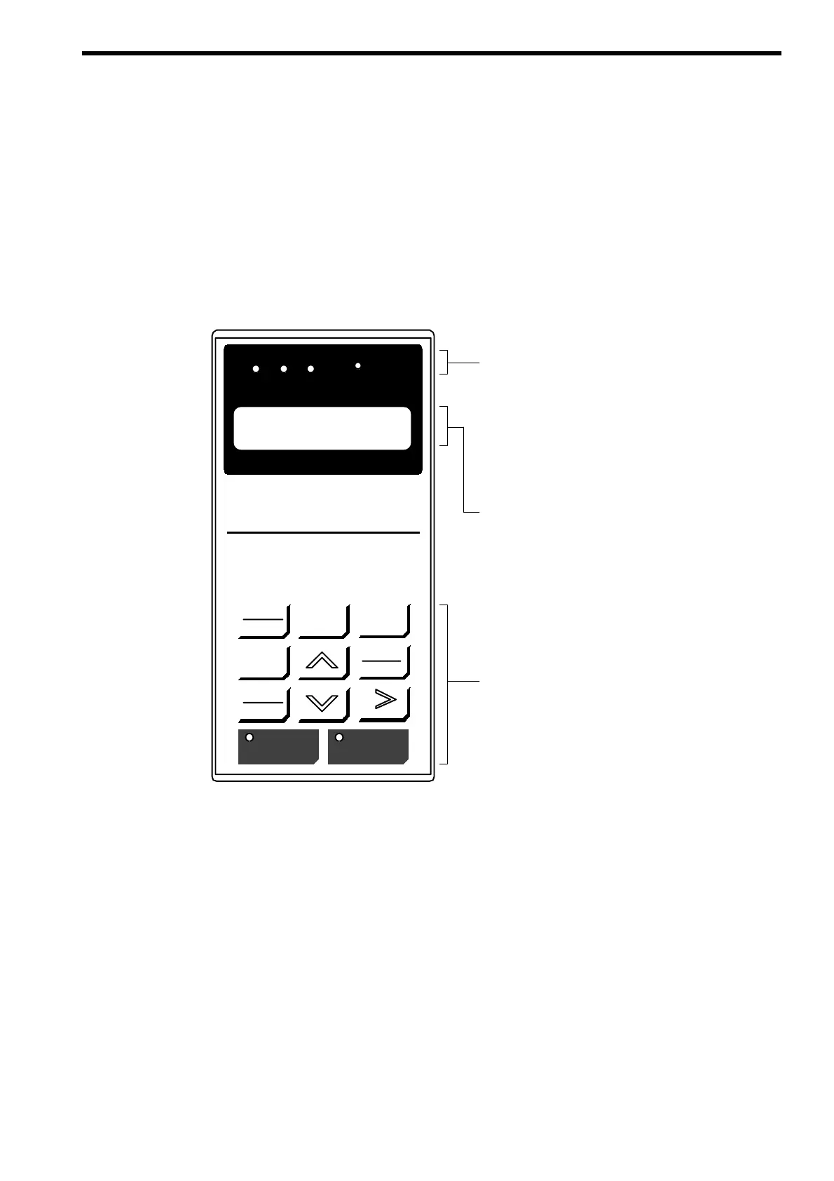
1.3 USING THE DIGITAL OPERATOR
This section describes the component names and functions of the Digital Operator.
The component names and functions are shown in Fig. A-2 and Key function are de-
scribed in Table A-1.
LOCAL
REMOTE
MENU
DIGITAL OPERATOR
JVOP-130
ESC
DATA
ENTER
JOG
FWD
REV
RESET
RUN STOP
DRIVE FWD REV REMOTE
SEQ REF
Dc Bus Voltage
U1-02 = 300 VDC
Keys
Execute operations such as setting user
constants, monitoring, JOG, and autotuning.
Data Display
Two-line LCD that displays data for monitor-
ing, user constants, and set values with 16
characters per line.
Operation Mode Indicators
DRIVE : Lit when in operation mode.
FWD : Not used
REV : Not used
SEQ : Lit when the run command from the
control circuit terminal is enabled.
REF : Not used
Fig. A-2 Digital Operator Component Names and Functions