<5. Basic Operating Procedures>
48
IM 01E24A01-01EN
5. Basic Operating Procedures
5.1 Operation by Display unit
The parameter settings from display unit can be carried
out using the three IR (infra-red) switches - namely, the
[SET] [SHIFT] and [▼] switches. The IR switches enable
the user to set parameters from the outside of the glass of
the display cover.
This section provides descriptions of basic parameter
conguration and operation procesures of IR switches.
This product can be also operated using the dedicated
handheld terminal or the FieldMate (Versatile Device
Management Wizard). For operation in details, read the
user’s manual of the applicable communication type
(for AXW/AXW4A) or the hardware/software edition (for
AXFA11) as listed in Table 1.1.
WARNING
Be sure to enable the write protect function to prevent
the overwriting of parameters after nishing parameter
setting.
In rare cases, the IR switches may respond
unexpectedly to water drops or extraneous substances
sticking on the surface of display panel, due to the
operating principal. The possibility of malfunction arises
after rain or cleaning operation near the place where the
owmeter is installed. Turning on and off the ashlight
etc. towards the IR switch may also be a cause of
malfunction.
Read Section 6.3 for the hardware write protect
function, and the user's manual of applicable
communication type as listed in Table 1.1 for the
software write protect function.
IMPORTANT
Operate the display unit under the condition where
direct sunlight, etc... do not shine to the IR switches
directly when the parameter setting operation is carried
out.
NOTE
• Always keep the cover closed and operate the
setting switches from the outside of the glass
window.
• If dirt, dust or other substances surfaces on the
glass of display cover, wipe them clean with a soft
dry cloth.
• The operation with dirty gloves may cause a switch
response error.
NOTE
The language on the display is set to “English” as default
at the factory shipment. Select the adequate language
referring to the Subsection 5.2.2. The menu pass of the
display on this manual is selected to “English”.
5.2 Display and Basic
Conguration
The display unit of AXW Integral Flowmeter and AXW4A/
AXG1A Remote transmitter has various functions below.
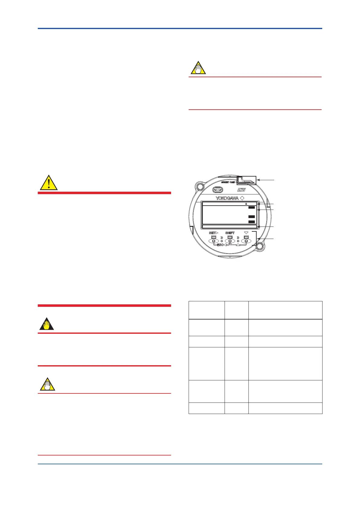
5.2.1 Display
microSD card
Status icon and time
Data display
(Abbreviation:
see Table 5.2.1)
Switch On/Off status
(On: inverted)
IR switches
22.000mA
0.0%
0.00000
m/s
00 : 00
VEL
FLP
A01
SET SFT INC
(1) Basic operation of IR switches
The operation from display panel is done by using
the three IR switches; [SET], [SHIFT] and [▼]. The
combination of the two switches provides a different
function, and the function is indicated on the display.
IR switch
(Note 1)
Indicate
of switch
(Note 2)
Function
[SET►] SET
▪ Apply parameter (Note 3)
▪ Enter data (Note 3)
▪ Move to next menu
[SHIFT] SFT
▪ Move cursor right
(Numeric type parameter)
[▼] INC
▪ Move cursor down
(Select type parameter)
▪ Increment value
(Numeric type parameter)
▪ Change position of decimal point
(Numeric type parameter)
[SHIFT] + [▼]
(=[▲])
DEC
▪ Move cursor up
(Select type parameter)
▪ Decrement value
(Numeric type parameter)
SHIFT + SET►
(=[ESC◄])
ESC
▪ Cancel
▪ Back to previous menu
Note 1: [A] + [B] (=[C]): The function is changed to switch [C]
when switch [B] is pushed while pushing switch [A].
Note 2: [SET], [SFT], [INC], [DEC] and [ESC] indicate the
assigned function in accordance with display mode at
that time.
Note 3: “Apply” and “Enter” are executed by pushing a switch
twice. If a switch after rst pushing a switch.
 Loading...

