<6. Operation>
57
IM 01E24A01-01EN
6. Operation
After the installation of sensor into process piping, the
wiring of input/output terminals, the conguration of
required parameters, and the zero adjustment prior to
peration, the owmeter outputs a ow signal from its
terminals as soon as the uid is sent in the pipe.
CAUTION
If any damages, such as cracks, breakage or
destruction on the glass of the display occurs, stop
using it and replace the cover. If it is used with
damaged glass, it may cause injury, electric shock,
malfunction, and specied protection performance of
the housing is not provided.
6.1 Pre-operation Zero
Adjustment
Zero adjustment is carried out to ensure that the output
for zero ow is 0% (i.e., 4 mA). Although adjustment to
zero is performed at the manufacturing plant prior to
shipment, this procedure must be carried out once again
following the installation of piping in order to match the
magnetic owmeter to its operating conditions.
This section describes the zero adjustment procedure
using the display unit. For AXFA11, read the applicable
user’s manual as listed in Table 1.1.
IMPORTANT
• Zero adjustment should be carried out before actual
operation. Note that parameter setting or change
cannot be carried out during execution of zero
adjustment (i.e., for approximately 30 seconds).
• Zero adjustment should only be carried out when
the sensor has been lled with measurement uid
and the uid velocity is completely zero by closing
the valve.
• Each time that the uid being measured is changed,
be sure to carry out zero adjustment with the new
uid.
6.2 Zero Adjustment from
Display Unit
A procedure of executing zero adjustment is as follows;
Display Menu Path:
Device setup ► Diag/Service ► Autozero ► Execute
Device setup ► Diag/Service ► Autozero ► Result ► Zero value
Enter the Setting Mode. (Read Section 5.3)
For F
OUNDATION
eldbus type, set mode of all transducer
blocks to “O/S” (Out of Service) before the adjustment.
After the adjustment, set mode of all transducer blocks to
“Auto”.
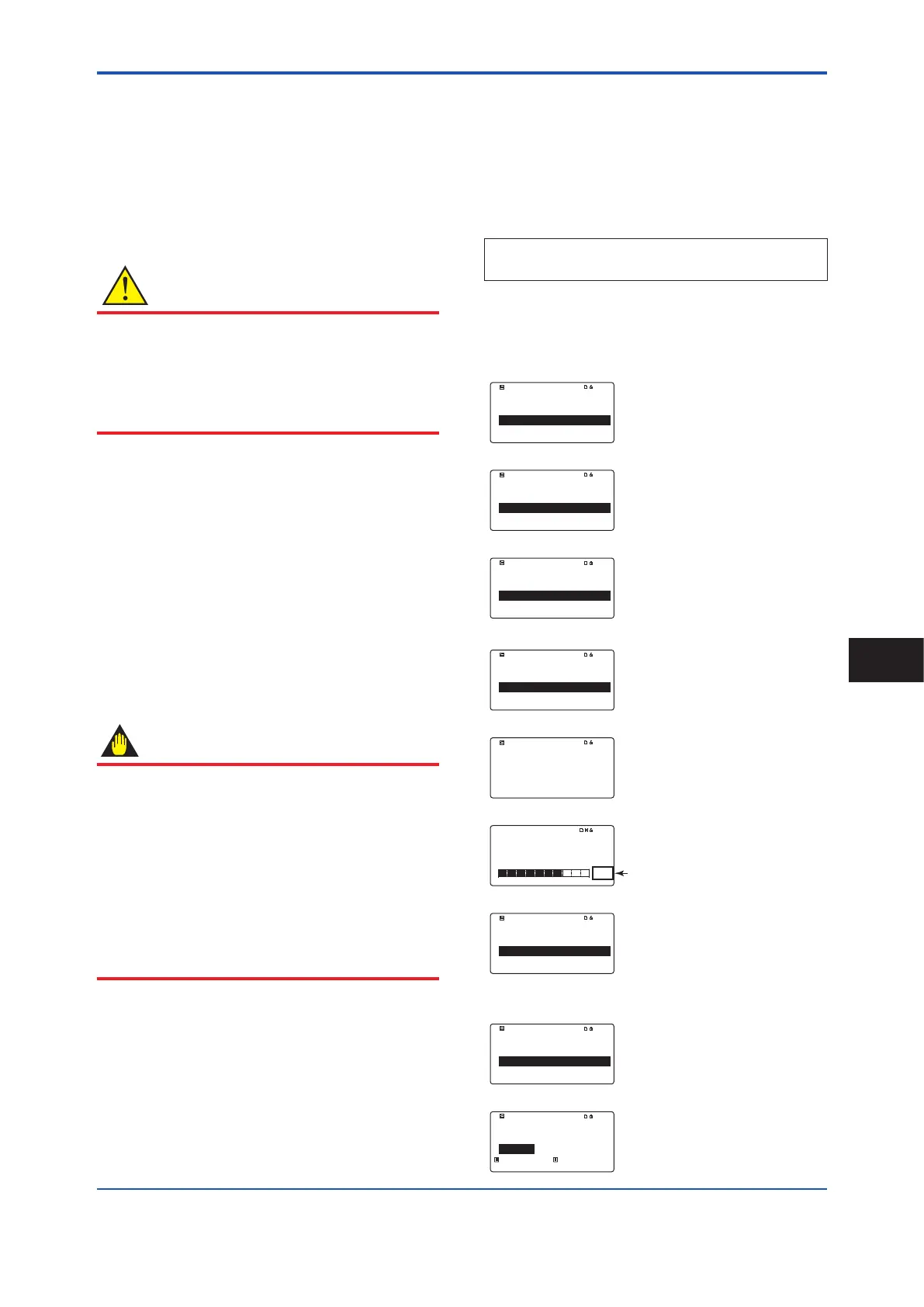
Device setup
Process variables
Diag/Service
Easy setup wizard
▲
▼
SET SFT INC
►
►
►
Select “Diag/Service” accoriding to the
menu path above.
Diag/Service
Verification
Autozero
AO/AI trim
▲
▼
00 : 00
SET SFT INC
►
►
►
Select “Autozero”.
*: Fieldbus communication type does not have
AO/AI trim.
Autozero
Execute
Result
▲
▼
SET SFT INC
►
Select “Execute”.
Execute
Not execute
Execute
Not execute
▲
▼
00 : 00
SET SFT INC
Select “Execute”.
Execute
Execute
SET SFT INC
When “Execute” blinks, touch [SET] to
execute.
Autozero function
executing...
00 : 00
00 : 08
SET SFT INC
until the end.
Autozero starts, and the progress is
desplayed with a remaining time and a
bar graph. Wait for the completion.
Autozero
Execute
Result
▲
▼
SET SFT INC
►
After Autozero nished, the display
returns to “Autozero” menu.
• Conrmation of zero adjustment result
Result
Zero value
▲
▼
00 : 00
SET SFT INC
For the result of Autozero, select “Result”
and then “Zero value”.
Zero value
– 00.018cm/s
– 00.018cm/s
– 99.999 + 99.999
SET SFT INC
Result of Autozero is indicated as on
the left.
Operation
6
 Loading...

