<6. Operation>
60
IM 01E24A01-01EN
NOTE
• If the hardware switch is set to “ON”, the condition of
preventing parameter overwriting kept until the switch
is set to “OFF”.
• For the software write protect, read the user’s manual
of applicable communication type as listed in Table
1.1.
● Setting of Address Switch (ADDRESS)
This switch is only available for the product with Modbus
communication.
For the product with Modbus communication, it is
necessary to set the device address.
The device address can be set using either the address
switch (ADDRESS) (See Figure 6.3.1) or software
function with parameter setting.
• Address Switch (Position 7)
By using the address switch (Position 7), select the
device address to be used from the device address
specied by either the hardware switch or the
parameter setting.
Table 6.3.5 Address switch (Position 7)
Position of Switch Description
The device address set by Address Switch
(Position 0 to 6) is used.
The device address set by parameter
setting is used.
Factory setting.
• Address Switch (Position 0 to 6)
By using the address switch (Position 0 to 6), the
device address is set.
Setting range: 1 to 127
If the address switch is set to 0, the device address is
automatically converted to 1.
Setting example:
If only the address switch “position 6” is set to 1, the
resulting the device address is 64.
(1 * 2
6
+ 0 * 2
5
+ 0 * 2
4
+ 0 * 2
3
+ 0 * 2
2
+ 0 * 2
1
+ 0 * 2
0
)
● Setting of Line Termination Switch (SW2)
This switch is only available for the product with Modbus
communication.
Line terminations of two ends on the bus are required to
communicate Modbus.
One termination mode can be set using the line
termination switch (SW2) (See Figure 6.3.1).
Table 6.3.6 Line termination switch (SW2)
Position of
Switch
Termination
mode
Description
ON
Bus end
Available when both SW2-1 and
SW2-2 are“ON”.
(Resistance is 150 Ω)
ON
Not bus end
Available when both SW2-1 and
SW2-2 are“OFF”.
Factory setting.
Both SW2-1 and SW2-2 must be set at the same position.
● Setting of Pull up and Pull down Switch
(SW3)
This switch is only available for the product with Modbus
communication.
When the bus is in an idling state, it becomes unstable
potentially without setting D1 for “pull up” and D0 for “pull
down”.
Pull up and pull down mode can be set using the pull up
and pull down switch (SW3) (See Figure 6.3.1).
Table 6.3.7 Pull up and pull down switch (SW3)
Position of
Switch
Pull up and
Pull down
mode
Description
ON
Used
Available when both SW3-1 and
SW3-2 are“ON”.
(Resistance : 600 Ω, Pull-up voltage:
+5 V)
ON
Not used
Available when both SW3-1 and
SW3-2 are“OFF”.
Factory setting.
Both SW3-1 and SW3-2 must be set at the same position.
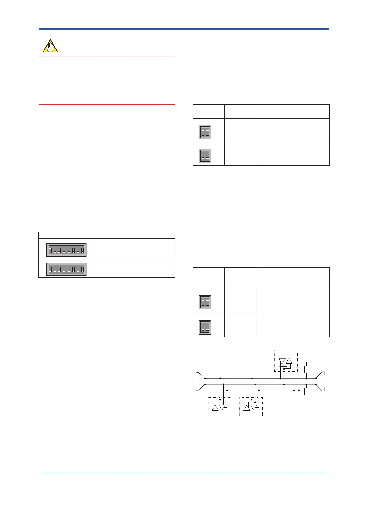
Master
Pull Up
Pull Down
Slave nADMAG
LT LTBalanced Pair
B A C
Common
D1 (+)
D0 (-)
D
R
D
D
R R
Figure 6.3.2 Modbus connection
 Loading...

