1-14
IM CA500-01EN
Connection Terminals
This instrument is equipped with the following two types of terminals.
TC-A terminal (TC mini plug)
A thermocouple is connected to the instrument using a thermocouple mini plug set, sold
separately. Reference junction compensation using an external RJ sensor (sold separately) is
not possible.
TC-B terminal (banana plug)
Reference junction compensation using the internal RJ sensor or an external RJ sensor is
possible.
Reference Junction Compensation
The instrument measures the temperature of the reference contact using an RJ sensor and
makes measurements based on that temperature.
This instrument can perform reference junction compensation using the internal temperature
sensor or an external RJ sensor.
When using the TC-A mini plug terminal, you cannot use an external RJ sensor.
Burnout
Thermocouple burnout is detected. When a burnout is detected, this instrument displays “B
OUT” on the screen.
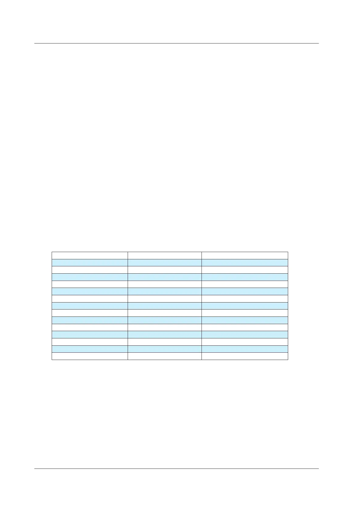
Temperature Measurement Using RTDs
Temperature is measured using the following RTDs.
RTD Measurement range Notes
PT100 (PT100 (3851)) -200.0°C to 800.0°C EC 60751
*
JPT100 (PT100 (3916)) -200.0°C to 510.0°C JIS C 1604 1989 (JPt100)
PT100 (3850) -200.0°C to 630.0°C JIS C 1604 1989 (Pt100)
PT100 (3926) -200.0°C to 630.0°C Minco Application Aid #18
PT200 -200.0°C to 630.0°C IEC 60751
*
PT500 -200.0°C to 630.0°C IEC 60751
*
PT1000 -200.0°C to 630.0°C IEC 60751
*
Cu10 -100.0°C to 260.0°C Minco Application Aid #18
Ni120 -80.0°C to 260.0°C Minco Application Aid #18
PT50 -200.0°C to 630.0°C IEC 60751
*
PT50G -200.0°C to 800.0°C GOST R 8.625-2006
PT100G -200.0°C to 630.0°C GOST R 8.625-2006
Cu50M -180.0°C to 200.0°C GOST R 8.625-2006
Cu100M -180.0°C to 200.0°C GOST R 8.625-2006
*: Complies also with JIS C 1604
Wiring Systems
The following RTD wiring systems are available: two-wire, three-wire, and four-wire.
Two-wire system: Because the resistance in the lead wires connecting the RTD and the
instrument is included in the measurement, errors become large. Use this when
the RTD and the instrument are close.
Three-wire system: By making the length of the three measurement lead wires connecting the
RTD and the instrument the same, measurements can be made without hardly
being affected by the resistance of the lead cables.
Four-wire system: Measurements can be made without being affected by the resistance in
the lead wires connecting the RTD and the instrument.
1.4 Measurement Function
 Loading...