IM 12A01A02-01E 7/11
8th Edition
Measuring Module 1, 2
Type of Measuring Module
pH, SC, DO ISC SENCOM
Uo 11.76 V 11.76 V
5.36 V
Io 116.5 mA 60.6 mA
106.16 mA
Po
0.3424 W 0.178 W 0.1423 W
Co
100 nF 100 nF 31 μF
Lo
1.7 mH 8 mH 0.45 mH
Specic condition of use
- Precautions shall be taken to minimize the risk from electrostatic discharge of non-metallic parts and
painted parts of the enclosure. When the equipment used in hazardous locations, avoid any action
which generate electrostatic discharge such as rubbing with a dry cloth.
- The cable gland accompanying the equipment may not provide sufcient clamping. Additional clamping
of the cable shall be provided to ensure that pulling and twisting are not transmitted to the termination.
Alternatively, an Ex d, Ex e, or Ex n cable gland which provides sufcient clamping shall be used
instead of the accompanying cable gland.
Notes:
1. Installation must be in accordance with EN60079-14 and relevant local codes.
2. Measuring Module 2 is not always installed. As for ISC module and SENCOM module, only one
module is permitted to be installed at a time.
3. For Zone 2 installation, Sensor 1 and Sensor 2 may be equipment suitable for Zone 2
Ui (or Vmax) ≥ Uo
Ii (or Imax) ≥ Io
Pi ≥ Po
Ci ≤ Co – Ccable
Li ≤ Lo – Lcable
4. FLXA202 Analyzer must be installed in accordance with one of the following:
a) in a SELV or PELV system, or
b) via a safety isolating transformer complying with the requirements of IEC 61558-2-6, or a technically
equivalent standard, or
c) directly connected to apparatus complying with IEC60950 series, IEC61010-1, or a technically
equivalent standard, or
d) fed directly from cells or batteries.
5. WARNING – POTENTIAL ELECTROSTATIC CHARGING HAZARD
CSA
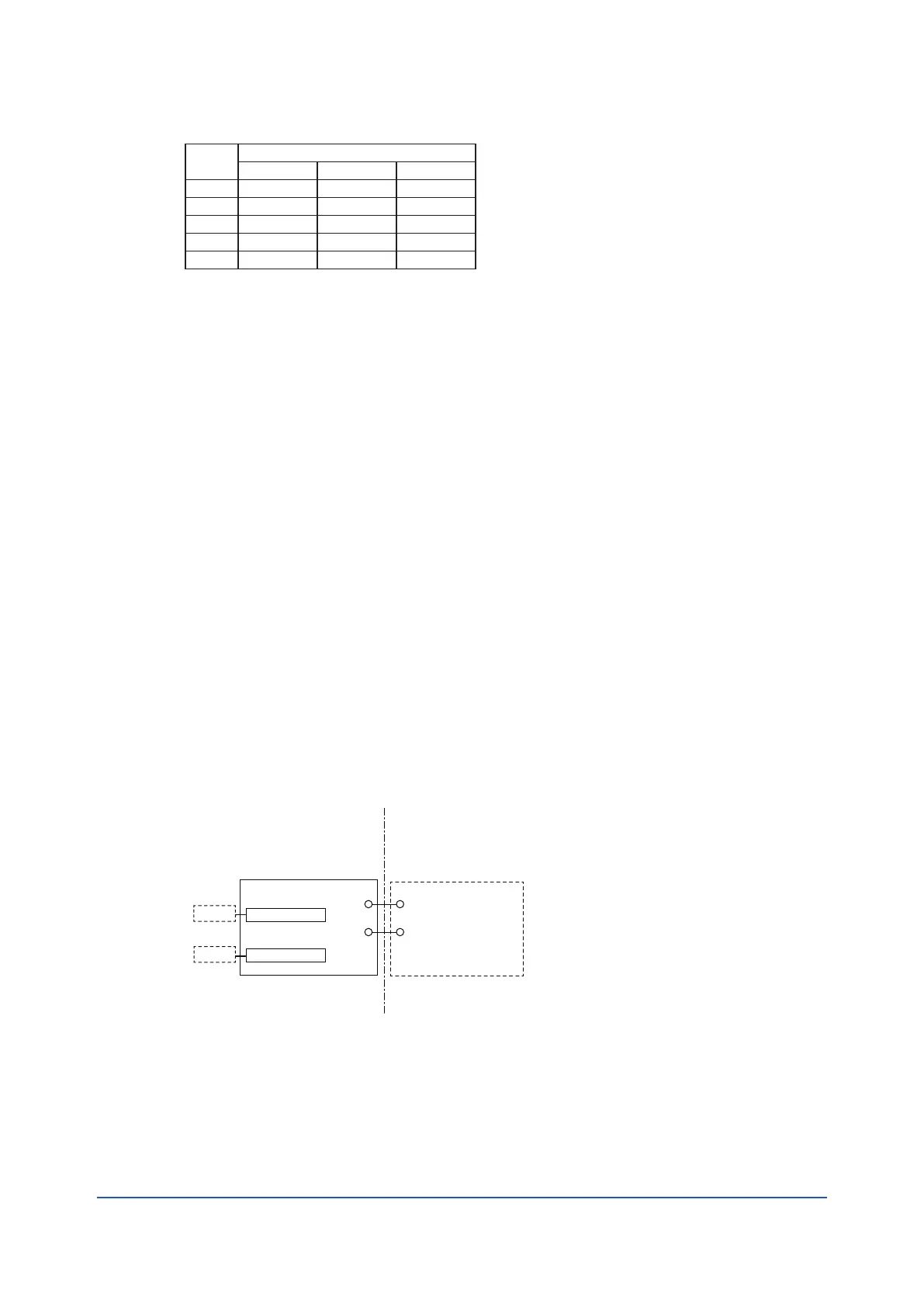
Control Drawing (for 4-20mA type)
Class I, Division 2, Groups A, B, C, D, or
Class I, Zone 2, Group IIC,
Temperature Class: T4
Measuring Module 1
Measuring Module 2
Sensor 1
Sensor 2
Power Supply /
Control Equipment
(Note 4)
Housing Assembly
FLXA202 Analyzer
Supply
Supply
Non Hazardous AreaHazardous Area
Ex nA ic Ratings
Supply +, Supply –
Um: 29.6 V
Un: 16V to 29.6V (pH/ORP,SC,DO one module)
17V to 29.6V (ISC one module)
21V to 29.6V (SENCOM one module)
22.8V to 29.6V (pH/ORP,SC, DO two modules)
NIFW Parameters
Supply +, Supply –
Ui: 30 V
Ci: 13 nF
Li: 0 mH
-
+
-
+