<2. WIRING AND INSTALLATION>
2-7
IM 12A01A02-01E 8th Edition : Oct. 01, 2015-00
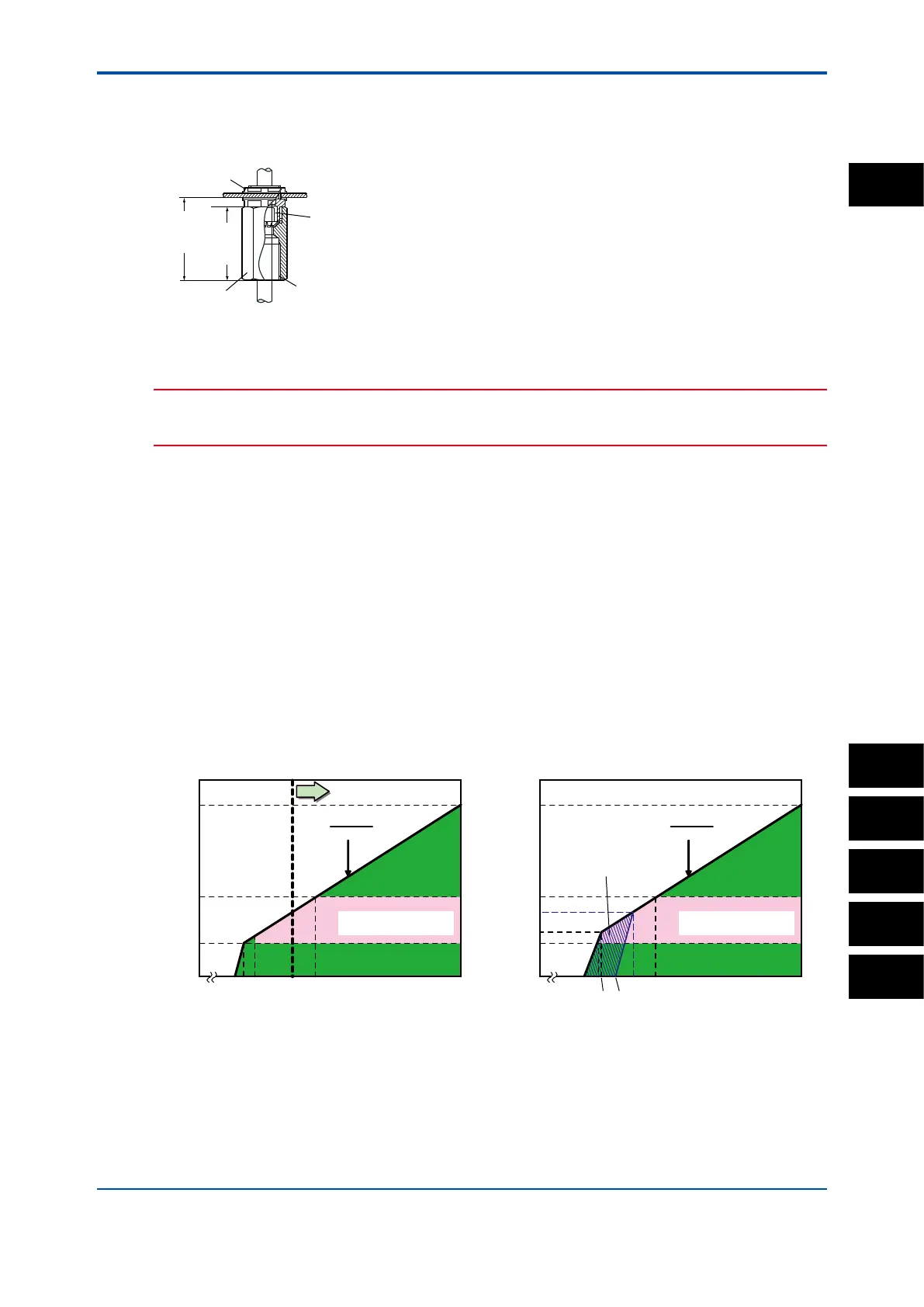
l Adapter for conduit work
When protecting the cable with a conduit, use an adapter (option codes: /CB4, /CD4, or /CF4).
Set the adapter as shown in gure 2.7, instead of using the cable gland as shown in gure 2.6.
Adapter
49
(1.93")
G1/2 screw (/CB4), 1/2 NPT screw (/CD4)
M20x1.5 screw (/CF4)
Approx.
55(2.2")
Packing
Unit: mm(inch)
Nut
F0204.ai
Figure2.7 Adapter for conduit work (option)
CAUTION
When using a cable conduit, use a exible conduit to avoid stress on the conduit adapter.
The stress on the conduit adapter may damage the housing.
2.4 Wiring the power supply
First make sure that the power supply is in accordance with the given specications.
Power Supply: Nominal 24 V DC loop powered system
The load resistance: impedance of electronic equipment: typically 250 Ohm.
Number of input modules: 1-sensor measurement or 2-sensor measurement.
One (1) Sensor module (1 input): 16 to 40V DC (for pH/ORP, SC and DO),
17 to 40V DC (for ISC), 21 to 40V DC (for SENCOM)
Two (2) Sensor modules (2 inputs): 22.8 to 40V DC (for pH/ORP, SC and DO)
Note: When the FLXA202/FLXA21 is used in the multi-drop mode of HART communication, the output signal is changed from 12.5 mA
DC to 4 mA DC just after the power is turned on. Enough power supply for the instruments is to be provided.
250
600
1000
0
24.718
V - 11.5
0.022
R =
1295
1617 22.8
4040
Voltage (V)
2-sensor measurement
Load resistance (Ω)
Digital Communication
Range (HART)
250
304
600
516
1000
0
24.7
18
V - 11.5
0.022
R =
1295
17
40
22.86
40
Except SENCOM
Voltage (V)
Load resistance (Ω)
Digital Communication
Range (HART)
18.2
21
<for pH/ORP (analog sensor), SC and DO> <for ISC and pH/ORP SENCOM sensor>
Figure 2.8 Supply Voltage and Load Resistance
Open the front panel and remove the wiring covers to make the terminal block accessible.
PH
SC
ISC
DO
SENCOM
2