7. EXPLOSION PROTECTED TYPE INSTRUMENTS
7- 3
All Rights Reserved. Copyright © 2006, Rota Yokogawa
IM 01R01B02-01E-E 5th edition October 01, 2020 -00
7.1.3 Installation
For general installation description chapter 3.1 must be regarded.
ConnectioninRAMChousing:
Connect the cable conductors of the eldbus cable to the eldbus terminals as followed (see also Figure 3.3):
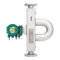
Table 7.4
Connector ST1
Variant Pin 1 Pin 2 Pin 3
#1 X X not used
#2 X X not used
#3 X X not used
#4 not used X X
Figure 7.1 Probus PA connector
If the eldbus device is operated as variant #1, #2 or #3, the supply voltage must be greater than 9.5 V
below an ambient temperature of 50 °C, and greater than 10 V above 50 °C.
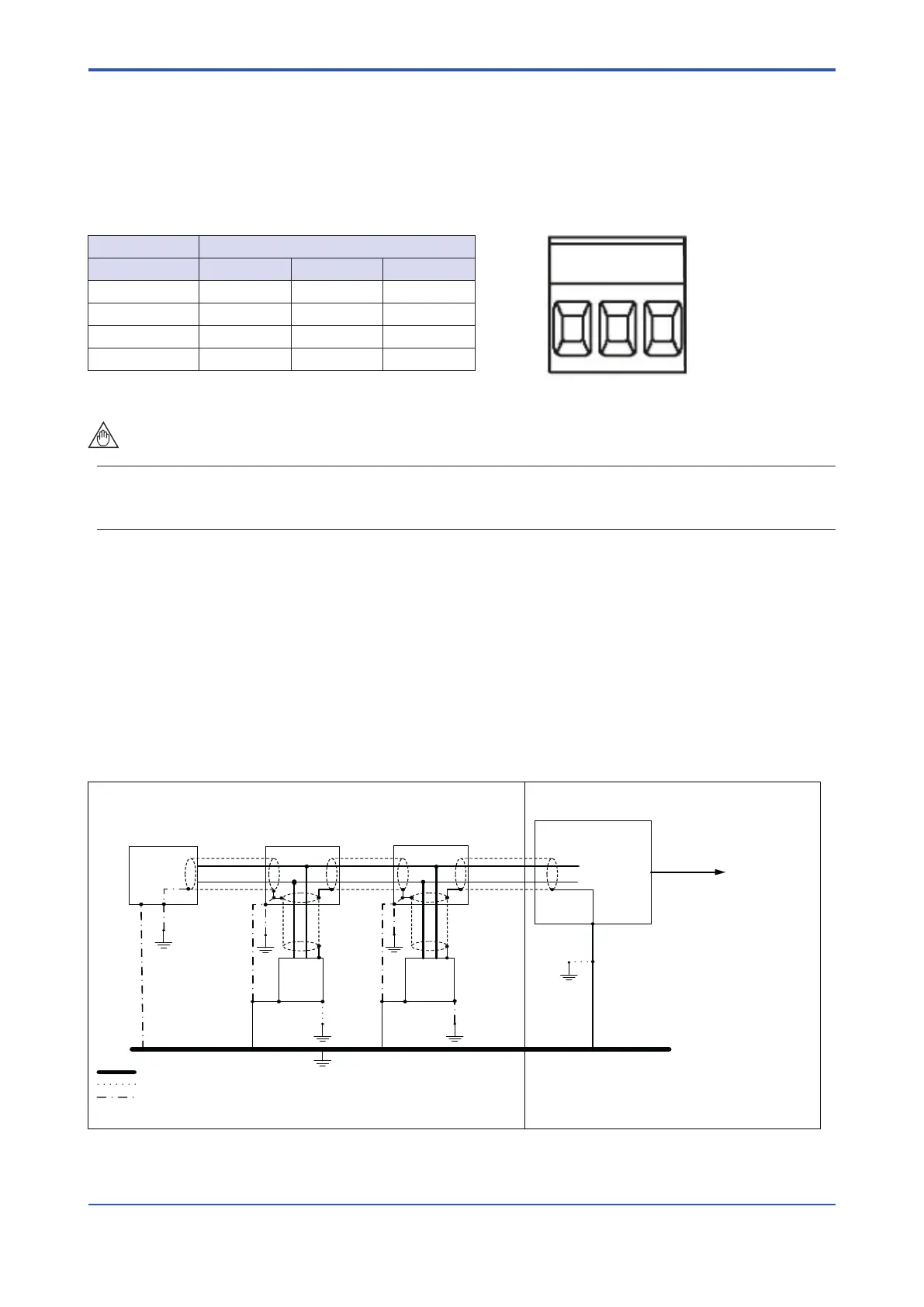
Groundingconnection:
Safe areaHazardous area
DP/PA-Coupler
Terminator
RAMC
PROFIBUS
PA
PROFIBUS DP
Host
FB +
FB -
Other
devices
T-Box
Ground Bonding System
Optional ground (needed if Ground Bonding System not used)
T-Box
According to manufacturer specification
If all devices connected to the BUS in the hazardous area are locally grounded according to
manaufacturers‘ specifications the Ground Bonding System could be avoided.
Figure 7.2
Possibility 1: Shield grounded in hazardous and safe area
3 2 1

 Loading...