3. INSTALLATION
3-1
All Rights Reserved. Copyright © 2006, Rota Yokogawa
IM 01R01B02-01E-E 5th edition October 01, 2020 -00
3.1 Wiring System Conguration
The number of devices that can be connected to a single bus and the cable length vary depending on
system design. When constructing systems, both the basic and overall design must be carefully considered
to allow device performance to be fully exhibited.
3.2 Connection of Devices
The following instruments are required for use with PROFIBUS PA devices:
• Terminator:
PROFIBUS PA requires two terminators at the end of the segment
•SegmentCoupler:
PROFIBUS PA requires the segment coupler which adopts to the RS-485 signals to the IEC 61158-2
signal level.
• Fielddevices:
Connect RAMC PROFIBUS PA communication type. Two or more RAMC devices or other devices can
be connected.
• Master:
Used for accessing eld devices. A dedicated master (such as DCS or PLC) is used for an instrumentation
line while dedicated communication tools are used for experimental purposes. For operation of the
master, refer to the instruction manual for each master. No details of the master are explained in the
rest of this manual.
• Cable:
The PROFIBUS specication must be regarded.
Two-core twisted and shielded cables are recommended, otherwise the EMC-requirements for
industrial ow meters can not be guaranteed.
EN 50170 species two types of bus cables. For transmission rates up to 1.5 Mbit/s, cable type A is
recommended.
3. Installation
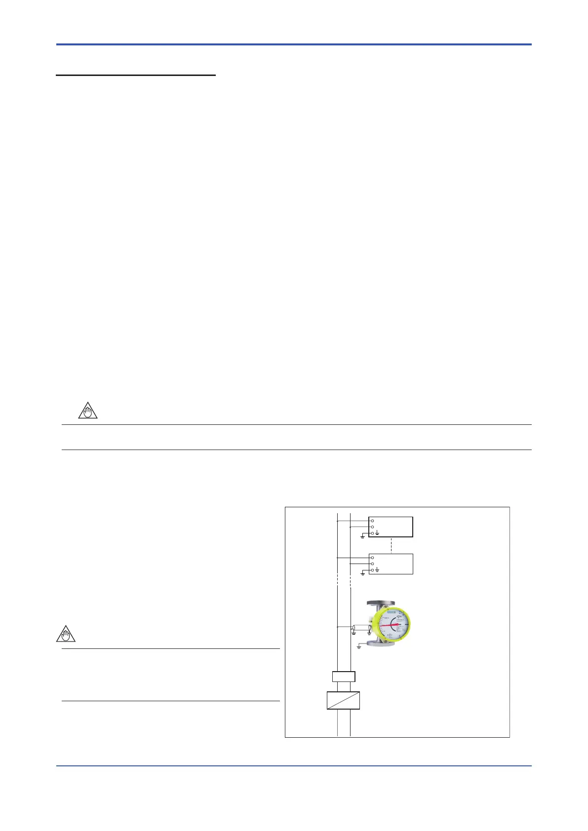
Figure 3.1 Device Connection
+
–
+
–
Field Instrument
Field Instrument
Te rminator
RAMC--P429
PROFIBUS PA
PROFIBUS DP
Segment
coupler
Grounding:
1) Device
2) Cable shield on bus side
3) Cable shield on transmitter side recommended
3)2)
1)
It is recommended to connect the shield on both
sides to ground. Compensation currents on ground
lines must be avoided. Therefore the shield may be
connected to ground on one side (e.g. in control
cubicle) via capacitor to ground.
The potential equalization must be connected
to the ow meter.
If the shield is only connected on supply side,
reduction of EMC immunity is possible.
In case of insufficient cable shielding and
grounding, degrading of EMC immunity is
possible.

 Loading...