The ESB bus are always dual-redundantly configured. When connecting or disconnecting the
connector unit for ESB bus, make sure the bus 1 and bus 2 are correctly identified and con-
nected.
l
ESB Bus Address Setting DIP Switches
When multiple node units are connected to an ESB bus, it is possible to select a node unit to
be accessed by setting the node address using these switches.
n
Setting Node Addresses
ESB bus node number can be defined by setting the Dip switches.
The node number can be designated in the range of 2 to 10 for a safety node unit that is con-
nected to SCSP1/SCSV1, or in the range of 2 to 14 for a safety node unit that is connected to
SCSP2. It is possible to match the required node numbers by setting the DIP switches as fol-
lows:
•
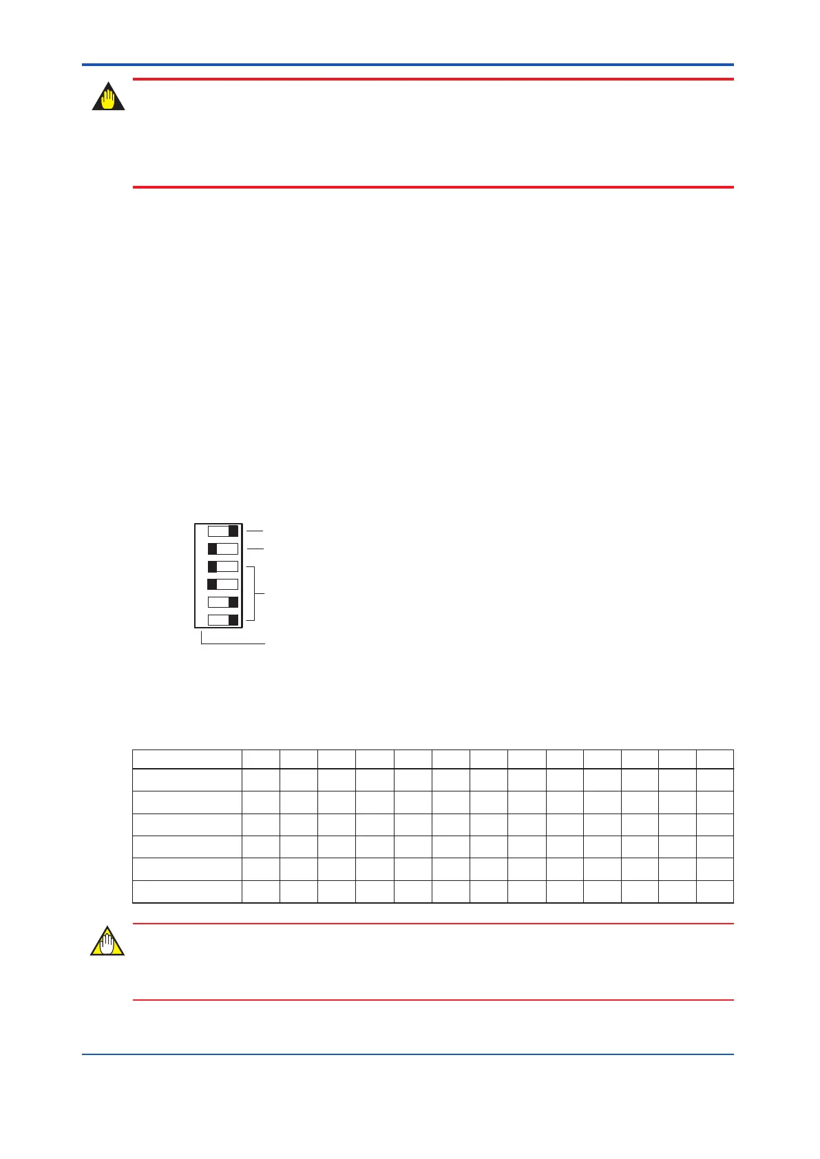
Setting DIP switches
0: In the state shown in the following figure, the switch is tilted toward the left.
1: In the state shown in the following figure, the switch is tilted toward the right.
Node number 1 is reserved for the safety control unit.
6
5
4
3
2
1
(LSB)
(MSB)
MSB : Most Significant Bit
LSB : Least Significant Bit
1
0
Fixed to 0
Node address parity (1 bit, odd parity)
Node address
Bit number
Figure 4.4-3 Node Number Setting DIP Switches
Table 4.4-1 Node Number and Switch Positions
Node number 2 3 4 5 6 7 8 9 10 11 12 13 14
Bit 1 0 1 0 1 1 0 0 1 1 0 1 0 0
Bit 2 0 0 0 0 0 0 0 0 0 0 0 0 0
Bit 3 0 0 0 0 0 0 1 1 1 1 1 1 1
Bit 4 0 0 1 1 1 1 0 0 0 0 1 1 1
Bit 5 1 1 0 0 1 1 0 0 1 1 0 0 1
Bit 6 0 1 0 1 0 1 0 1 0 1 0 1 0
Make sure that the node number setting DIP switches are correctly set.
<4.4 ESB Bus Interface Module > 4-16
IM 32Q06C10-31E 4th Edition : Jan.30,2015-00
 Loading...
