8.3.1 Connecting to Digital I/O Modules
SEE
ALSO
For more information about cables for connecting to digital I/O modules, refer to:
“n Combinations of Input/Output Module and Terminal Block” on page 5-3
n
Cable Connection
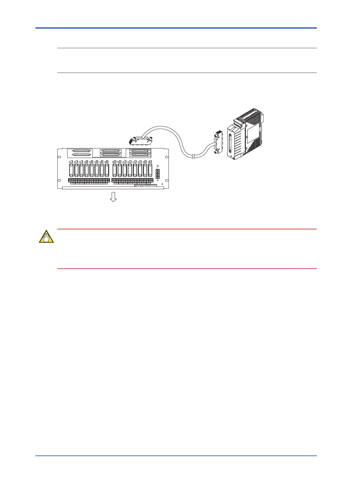
A connection example is shown in the following figure.
Field Cable
Digital I/O Module
with signal cable interface adapter
Signal cable
Relay Board
Figure 8.3.1-1 Cable Connection
For the connectors with no cable connected, it is necessary to put the connector caps so as to
protect the pins of the connectors from the dust pollution.
n
Fixing Signal Cables
Secure the signal cables, connected to the relay board, to the supporting frames using the
binding bands at the top of the relay board. The following figure shows an example of a 19-
inch rack mountable relay board.
<8.3 Cable Connection > 8-5
IM 32Q06C10-31E 4th Edition : Jan.30,2015-00
 Loading...
