7.1.1 Inspection by Status Display LEDs
This section explains how to inspect modules installable on safety control units, safety node
units, and unit for optical bus repeater module.
n
Inspection of LEDs
Power supply modules, processor modules, bus interface modules, and I/O modules have
status display LEDs. It can easily be identified whether or not a module is operating normally
by checking whether these LEDs are turned on or of
f.
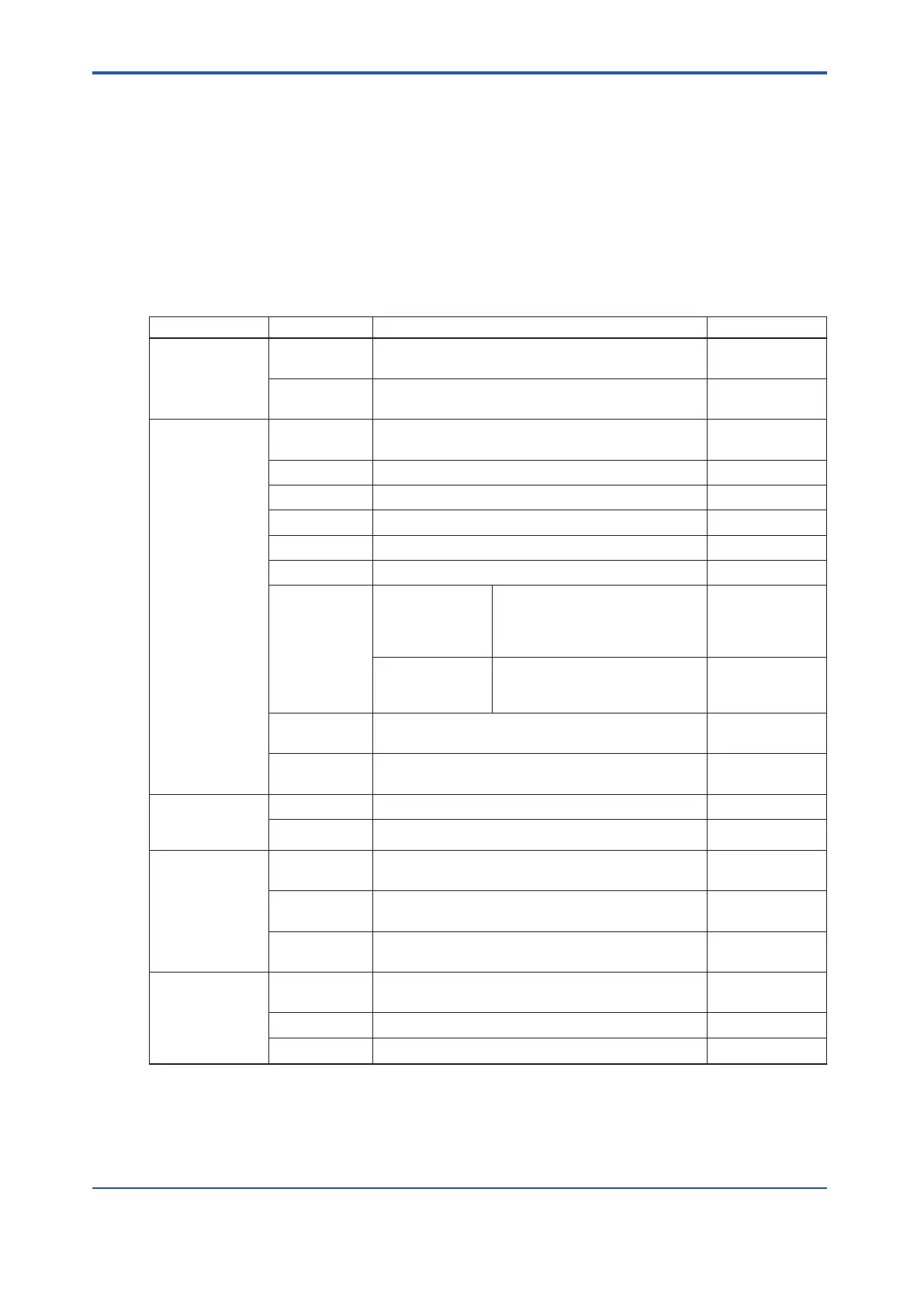
Table 7.1.1-1 Types and Functions of Status Display LEDs of Common Modules
Modules name Indicator Meaning of ON Meaning of OFF
Power supply
module
SYS +5 V output normal +5 V output ab-
normal
FLD +24 V output normal +24 V output ab-
normal
Processor
module
HRDY Hardware normal Hardware abnor-
mal
RDY Ready for control Module abnormal
CTRL Module is operating normally Module stand-by
COPY Copying Not copying
RCV-1, 2 Control bus1/bus2 in reception (*1) Not receiving
SND-1, 2 Control bus1/bus2 send status(*1) Not sending
SYNC SCP401 Synchronizes with V net clock or
IRIG-B clock
Cannot syn-
chronize with V
net clock or IRIG-
B clock
SCP461/SCP451 Synchronizes with Vnet/IP clock Cannot syn-
chronize with
Vnet/IP clock
SCTY SCS Security: Online level SCS Security:
Of
fline level
STATUS-1 to 8 Action mode/error status; domain and station num-
bers
-
ESB bus coupler
module
SEC401
RCV Receiving ESB bus frames from node units Not receiving
SND Sending ESB bus frames to node units Not sending
ESB bus coupler
module
SEC402
RCVL Receiving responses from node units through ESB
Bus lower port
Not receiving
RCVU Receiving responses from node units through ESB
Bus upper port
Not receiving
SND Sending commands to node units through ESB Bus
lower or upper port
Not sending
ESB bus
interface
module
STATUS Hardware normal Hardware abnor-
mal
SEL In data transmission to I/O module Not sending
RSP In data reception from I/O module Not receiving
Continues on the next page
<7.1 Routine Maintenance of Safety Control Unit > 7-3
IM 32Q06C10-31E 4th Edition : Jan.30,2015-00
 Loading...
