4.3 ESB Bus Coupler Module
ESB bus coupler module (Model: SEC401) is installed in the safety control unit for communi-
cating with the ESB bus interface module (Model: SSB401) installed in the safety node unit.
The ESB bus coupler module is always dual-redundantly configured.
ESB bus coupler module (Model: SEC402) is installed in the safety control unit (SSC60S/
SSC60D) for communicating with the ESB bus interface module (Model: SSB401) installed in
the safety node unit. The ESB bus coupler module is always dual-redundantly configured.
n
Configuration
SNDRCV
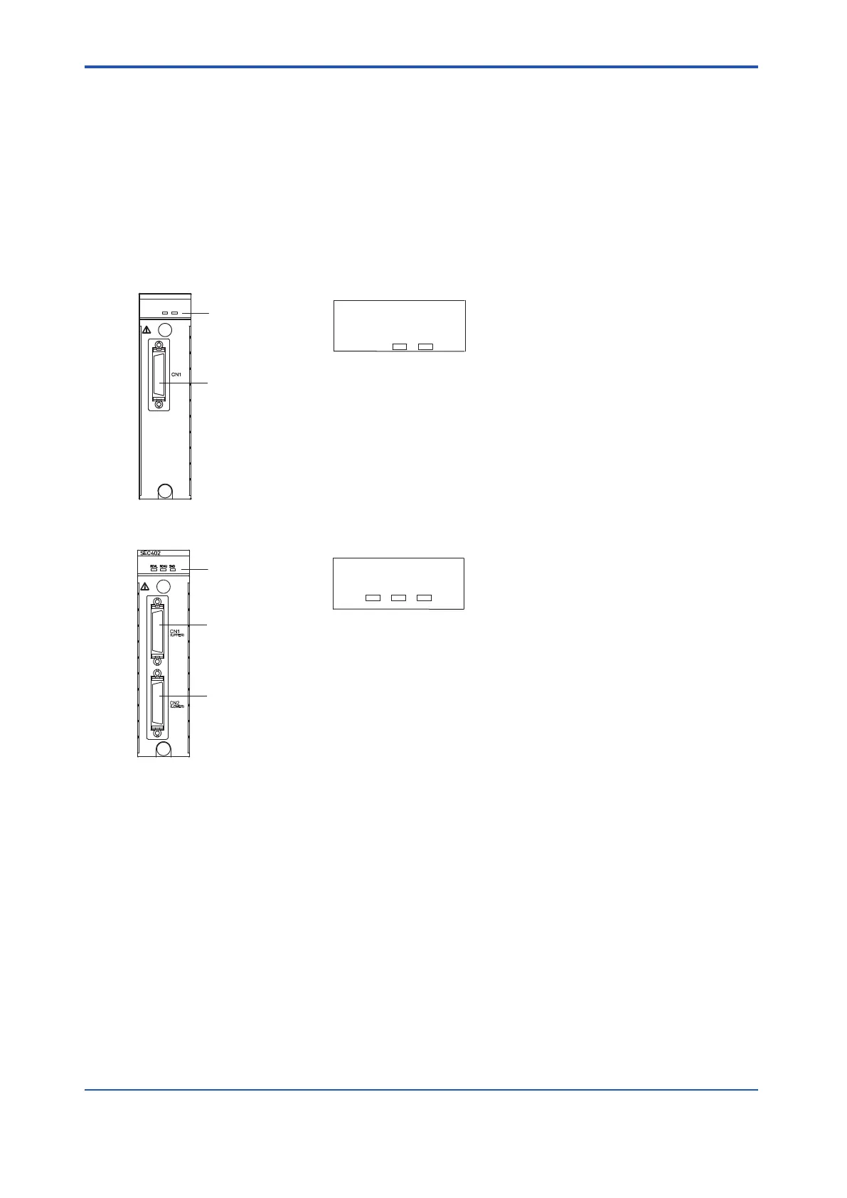
LED display close-up
SEC401
LED display
ESB bus cable connector
Figure 4.3-1 SEC401
SNDRCVU
RCVL
LED display close-up
LED display
ESB Bus Cable Connector (LOWER)
ESB Bus Cable Connector (UPPER)
Note: If a connector is not used, it should be covered with an attached connector cap.
Figure 4.3-2 SEC402
l
LED Display (SEC401)
•
RCV: When receiving ESB bus communication frames from safety node units, the LED
flashes, otherwise the LED is off.
• SND: When sending ESB bus communication frames to safety node units, the LED flash-
es, otherwise the LED is off.
l
LED Display (SEC402)
• RCVL: When receiving response frames from the safety node units through the lower
side port, the LED flashes, otherwise the LED is off.
• RCVU: When receiving response frames from the safety node units through the upper
side port, the LED flashes, otherwise the LED is off.
• SND: When sending command frames to safety node units through the lower side port or
the upper side port, the LED flashes, otherwise the LED is off.
<4.3 ESB Bus Coupler Module > 4-13
IM 32Q06C10-31E 4th Edition : Jan.30,2015-00
 Loading...
