4.6 V net Coupler Unit
The V net coupler unit (Model: AIP504) is installed in the safety control unit and located be-
tween the processor module and the V net cable so as to perform the signal isolation and sig-
nal level conversion.
n
Configuration
T
wo V net couplers are used because V net is a dual-redundant. The one installed in the left
is for Bus 1.
CN2
(CPU-L)
CN3
(CPU-R)
CN1
ENBL
DSBL
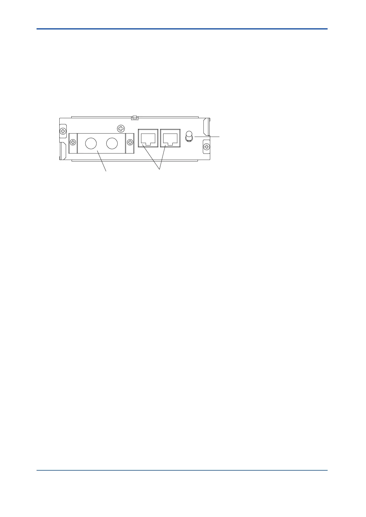
V net branch connector
Connector for V net coupler cable
Communication switch
Figure 4.6-1 V net Coupler Unit
l
V net Branch Connector
V net branch connector is used for the connection of V net cables (10BASE-2).
l
V net Coupler Cable Connector
When connecting the V net coupler unit and processor module, the V net coupler cable is
used for connection. The connector is modular type with a polarization key
.
l
Communication Switch
• ENBL (up):
Connects bus to the processor module. Leave the switch in this position normally.
• DSBL (down):
Disconnects bus from the processor module.
This is a locking type switch.
To toggle the switch position, pull the switch lever to unlock it first.
The upper side is ENBL and the lower side is DSBL.
<4.6 V net Coupler Unit > 4-20
IM 32Q06C10-31E 4th Edition : Jan.30,2015-00
 Loading...
