5.6 Circuit Diagrams of Input/Output Modules
A circuit diagram of the connections between an I/O module and a terminal board is shown as
follows.
n
Analog Input/Output Modules
The following table shows the relationship between analog input/output modules and terminal
boards.
Table 5.6-1 Relationship Between analog input/output modules and terminal boards
Analog input/output module (type) Connectable terminal board (type)
SAI143 SEA4D/SBA4D
SAV144 SEA4D/SBA4D
SAT145 SBT4D
SAR145 SBR4D
SAI533 SEA4D/SBA4D
l
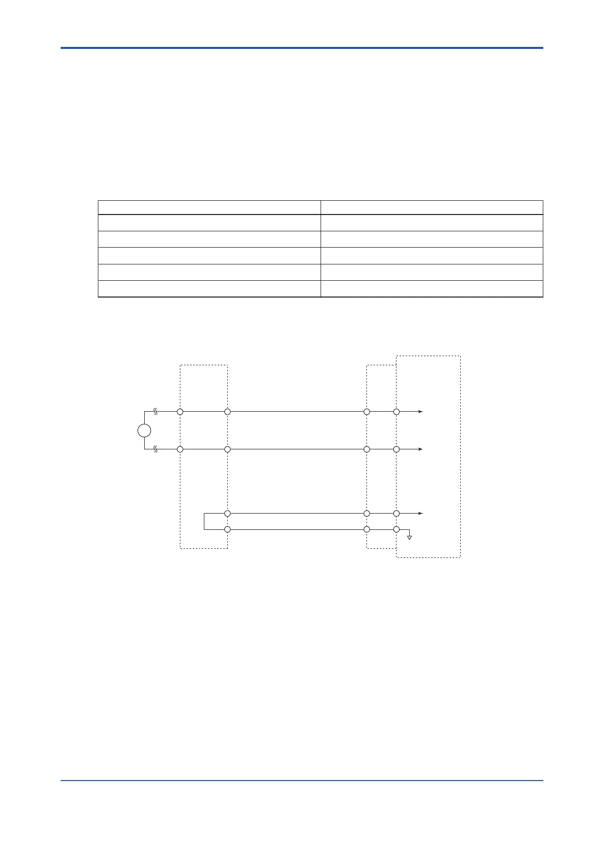
Analog Input Module (Current Input) : SAI143
INnA
INnB
INnA
INnB
CBSE
CBSE
CBSE
CBSE
CBSE
INnA
INnB
Analog
input module
Signal cable
interface adapter
Current
input
Signal cable
Terminal board
n : channel number
Figure 5.6-1 SAI143 Circuit Diagram
<5.6 Circuit Diagrams of Input/Output Modules > 5-47
IM 32Q06C10-31E 4th Edition : Jan.30,2015-00
 Loading...
