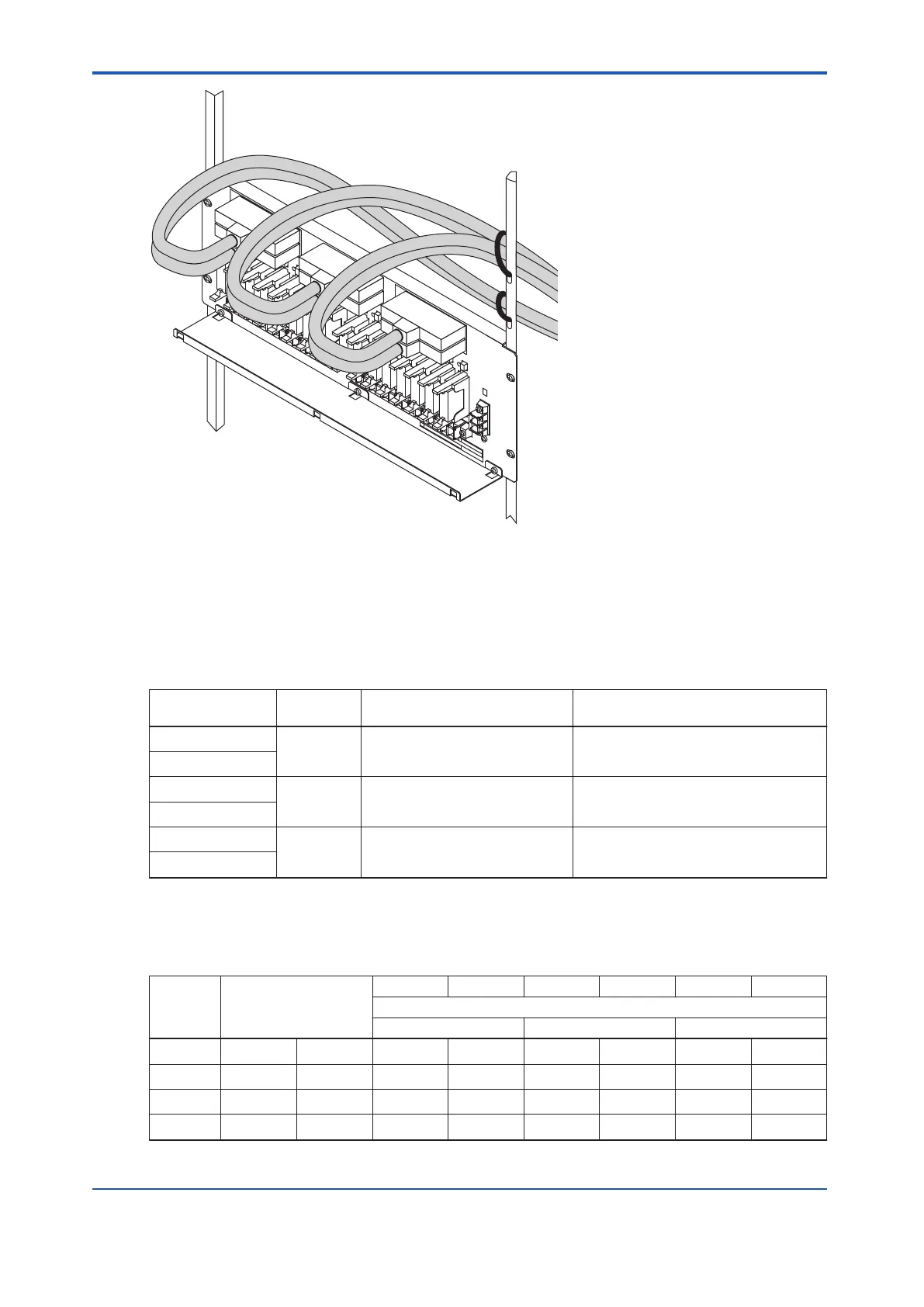
Figure 8.3.1-2 Example of Fixing the Signal Cables to the Right Pole
n
Connecting SRM53D to Digital I/O Modules
The following table shows the relations of the digital I/O modules connector numbers and the
connected field terminal numbers.
Table 8.3.1-1 Connector Numbers and Connected Field Terminal Numbers
Connector num-
ber
Connection Field terminal number Remarks
CN1
SDV531 TM1 (1-8) CN1/CN2 redundancy
CN2
CN3
SDV144 TM1 (1-8), TM2 (1-8) Readback; CN3/CN4 redundancy
CN4
CN5
SDV531 TM2 (1-8) CN5/CN6 redundancy
CN6
The following table shows the relations among the relay numbers, the field terminals, the digi-
tal output module connectors and the SDV531/SDV144 channel numbers.
Table 8.3.1-2 Relay Numbers/ Field Terminals/ Channel Numbers
Relay
number
(*1
)
Field terminal
CN1 CN2 CN3 CN4 CN5 CN6
SDV531/SDV144 Channel number
SDV531 SDV144 SDV531
1 TM1 1A/1B ch1 ch1 ch1 ch1 - -
2 TM1 2A/2B ch2 ch2 ch2 ch2 - -
3 TM1 3A/3B ch3 ch3 ch3 ch3 - -
4 TM1 4A/4B ch4 ch4 ch4 ch4 - -
Continues on the next page
<8.3 Cable Connection > 8-6
IM 32Q06C10-31E 4th Edition : Jan.30,2015-00
 Loading...
