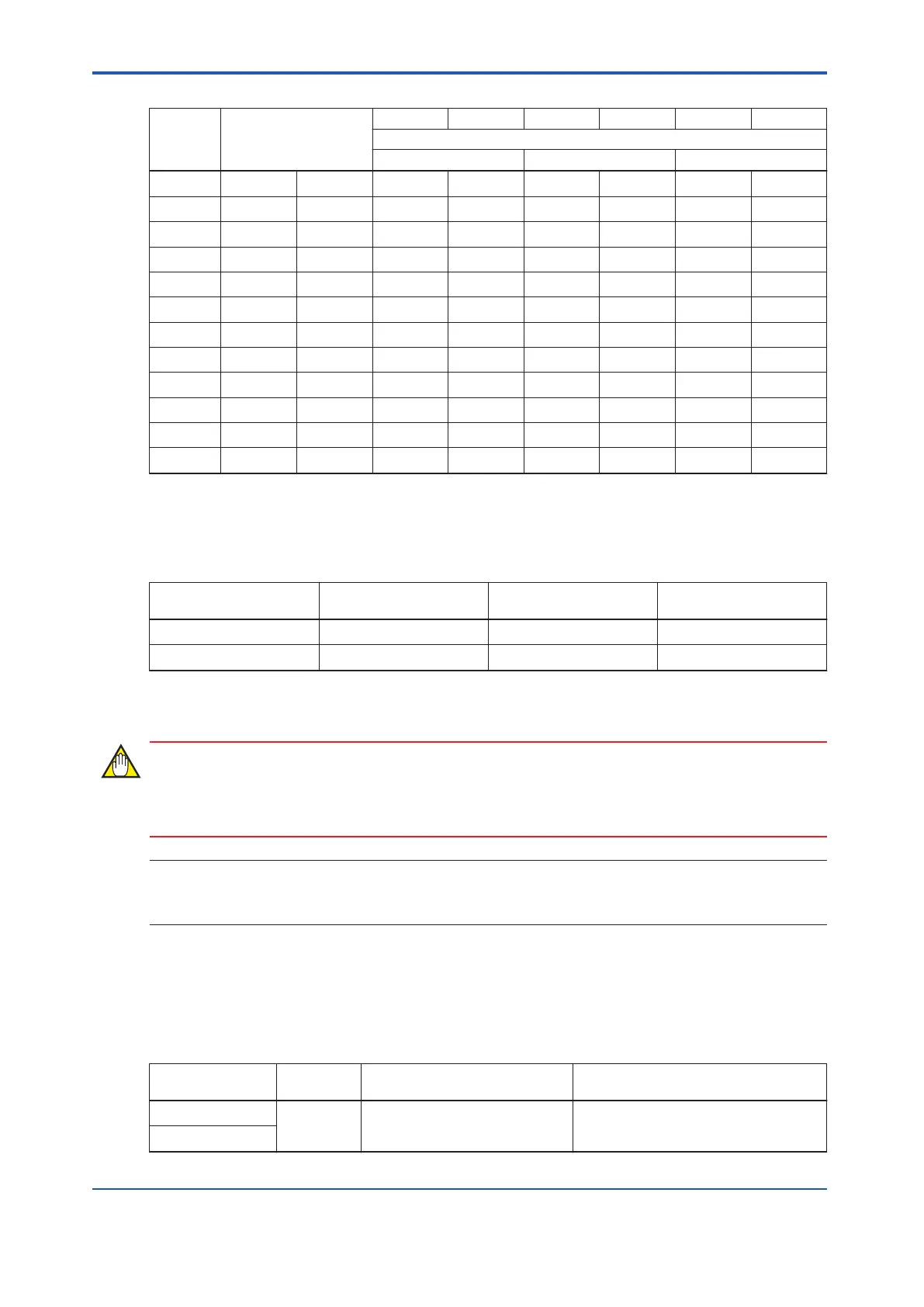
Table 8.3.1-2 Relay Numbers/ Field Terminals/ Channel Numbers (T
able continued)
Relay
number
(*1)
Field terminal
CN1 CN2 CN3 CN4 CN5 CN6
SDV531/SDV144 Channel number
SDV531 SDV144 SDV531
5 TM1 5A/5B ch5 ch5 ch5 ch5 - -
6 TM1 6A/6B ch6 ch6 ch6 ch6 - -
7 TM1 7A/7B ch7 ch7 ch7 ch7 - -
8 TM1 8A/8B ch8 ch8 ch8 ch8 - -
9 TM2 1A/1B - - ch9 ch9 ch1 ch1
10 TM2 2A/2B - - ch10 ch10 ch2 ch2
11 TM2 3A/3B - - ch11 ch11 ch3 ch3
12 TM2 4A/4B - - ch12 ch12 ch4 ch4
13 TM2 5A/5B - - ch13 ch13 ch5 ch5
14 TM2 6A/6B - - ch14 ch14 ch6 ch6
15 TM2 7A/7B - - ch15 ch15 ch7 ch7
16 TM2 8A/8B - - ch16 ch16 ch8 ch8
*1: The relay number is the number printed on the SRM53D metal body above each relay.
The output status, the LED status and the SDV144 readback status are shown in the follow-
ing table.
Table 8.3.1-3 Output Status, LED status and SDV144 Readback Status
SDV531 Output status
(*1)
LED status Field terminal status
SDV144 readback sta-
tus(*1)
OFF OFF (*2) OFF (Open) ON (Close)
ON ON ON (Close) OFF (Open)
*1: The output contacts are A type (NO: Normally Open), and SDV144 status contacts are B type (NC: Normally Close).
*2:
If the ON pulse diagnosis for SDV531 is enabled and the SDV531 output status is set to OFF, the LED goes ON for each ON
pulse output.
When SDV144 is connected to SRM53D, Detect Disconnection and Detect Short Circuit
should be disabled on I/O Parameter Builder.
SEE
ALSO
For more information about settings on I/O Parameter Builder, refer to:
A4.6, “Items set for discrete inputs” in Safety Control Station Reference (IM 32Q03B10-31E)
n
Connecting SRM54D to Digital I/O Modules
The following table shows the relations of the digital I/O modules connector numbers and the
connected field terminal numbers.
Table 8.3.1-4 Connector Numbers and Connected Field Terminal Numbers
Connector num-
ber
Connection Field terminal number Remarks
CN1
SDV541
TM1 (1-8),
TM2 (9-16)
CN1/CN2 redundancy
CN2
Continues on the next page
<8.3 Cable Connection > 8-7
IM 32Q06C10-31E 4th Edition : Jan.30,2015-00
 Loading...
