n
Configuration
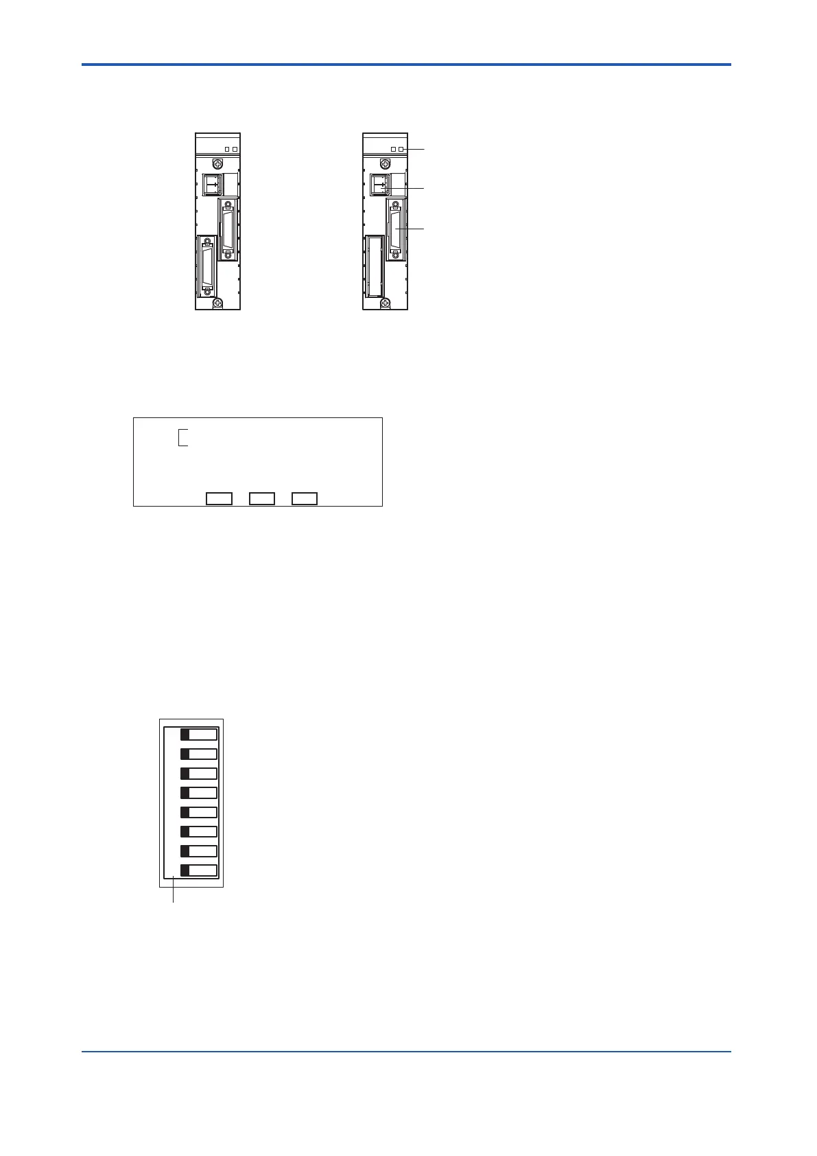
Fiber-optic cable connecter
ESB bus cable connector
SNT401/SNT411 : Without terminator SNT401/SNT411 : With terminator
SNT501/SNT511
LED display
Figure 4.5-1 Optical ESB Bus Repeater Module
l
LED Display
RCV 1
SND 1
STATUS
RCV
SND
OPT
NODE 1
Figure 4.5-2 LED Display
•
STATUS: If the self-diagnosis is successfully completed, the green lamp turns on.
• RCV/SND: If the ESB bus frame is received or sent, the green lamp turns on.
• OPT RCV-1/OPT SND-1: If the optical transmission frame is received or sent, the green
lamp turns on.
• NODE-1: If the DIP switch 1 is set to 1 (Node), the green lamp turns on.
l
DIP switch
1
0 1
NODE
Switch number
8
2
3
4
5
6
7
Figure 4.5-3 DIP switch
Set the DIP switch to indicate which unit the optical ESB bus repeater module is mounted on-
to. Remove the connector unit with terminator for ESB bus before changing the DIP switch
setting.
•
Switch 1: “0” if the module is mounted onto the unit for optical bus repeater module.
<4.5 Optical ESB Bus Repeater Module > 4-18
IM 32Q06C10-31E 4th Edition : Jan.30,2015-00
 Loading...
