*1: Outputs are in accord with the specification of SDV526.
*2:
SWD2D is supplied from external power supply and outputs voltage via SDV526.
SEE
ALSO
For more information about the specifications of the outputs of SDV526, refer to:
Digital I/O modules (for ProSafe-RS) (GS 32Q06K40-31E)
l
ALM T
erminals on SWD2D
Each terminal group has a pair of ALM terminals for sending a contact signal when fuse is
broken. When any fuse (1A to 4A, 1B to 4B, L and N) of a terminal group is broken, the con-
tact of the ALM terminals becomes closed. When all the fuses of the terminal group are nor-
mal, the contact of the ALM terminals stays open.
When the external relays are connected, a surge absorber should be used for inhibiting the
noises.
n
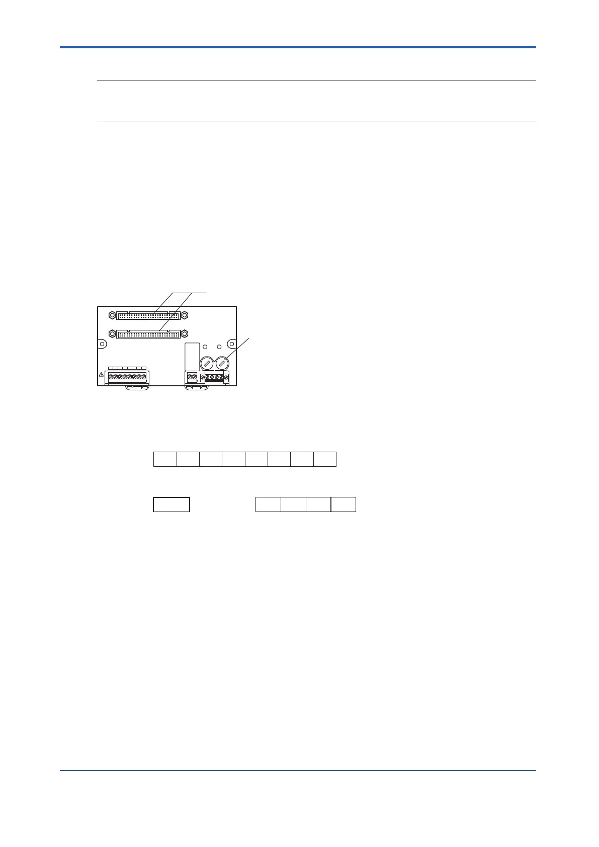
Connection Between SBD2D and an Output Module
CN1
CN2
1A 1B 2A 2B 3A 3B 4A 4B
POWER1
POWER2
FUSE1
250V 15A
FUSE2
250V 15A
READY
Connect to both the CN1 and CN2
connectors if the I/O modules are used
in a dual-redundant configuration.
Fuses (15A 2 Pieces)
Figure 5.4.4-11 SBD2D Terminal Board
l
When Connecting SDV521 (24 V DC Power Supply Required)
1A 1B 2A 2B 3A 3B 4A 4B
OUT1 COM1 OUT2 COM2 OUT3 COM3 OUT4 COM4
24V DC COM 24V DC COM
1+ 1- 2+ 2-
READY
READY
Signal Name
Terminal No.
Signal Name
Terminal No.
Signal Name
Terminal No.
Figure 5.4.4-12 SDV521 Signal Name and Terminal Number
l
READY Terminals on the SBD2D
When statuses of power supply and fuses are all normal, the output from READY terminals
will be energized, i.e., the contact becomes closed. When power supply fails or any of the
fuses fails, the output from READY terminals will be de-energized, i.e., the contact becomes
opened.
If an external relay is used, a surge absorber should be used for noise prevention.
l
LED Status
When the power supply is normal, the LED is on. Otherwise, the LED is off.
<5.4 Signal Cable Connection to Digital Input/Output Modules > 5-31
IM 32Q06C10-31E 4th Edition : Jan.30,2015-00
 Loading...
