n
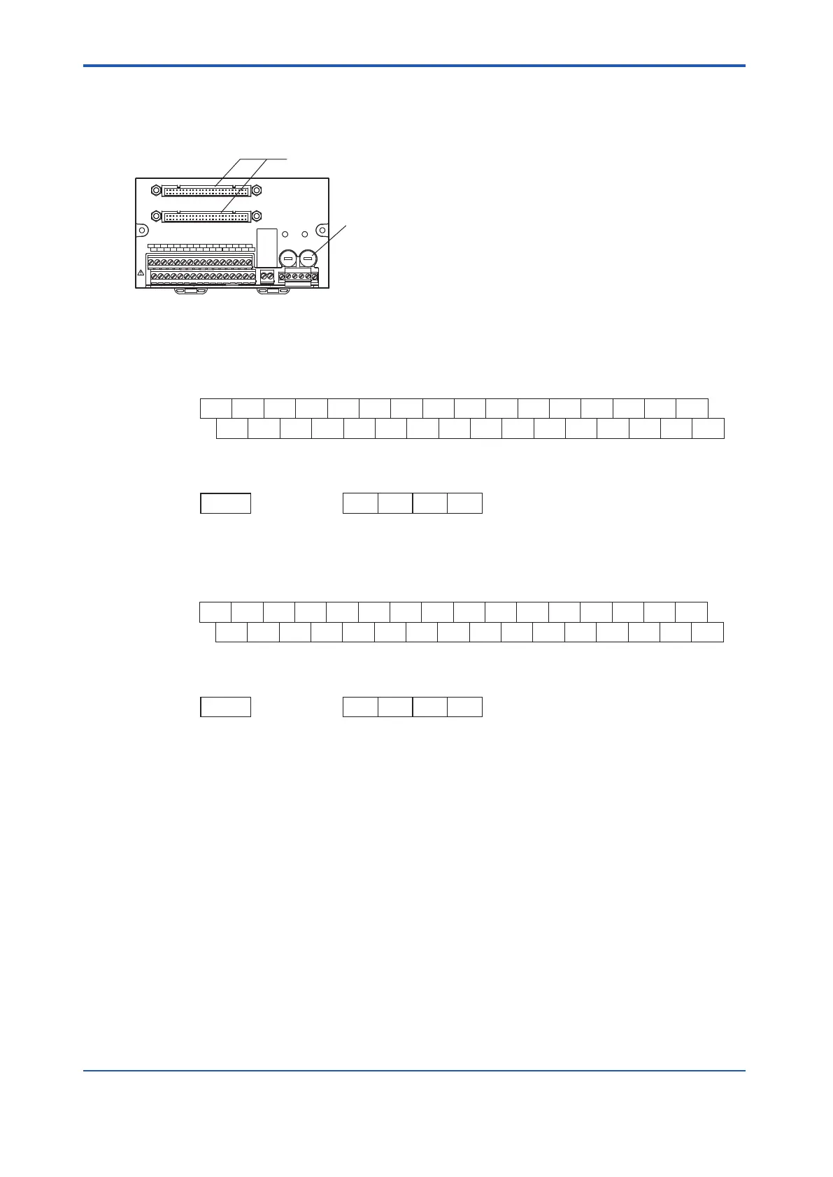
Connection Between SBD4D and an Input/Output Module
CN1
CN2
POWER1
POWER2
READY
1A 2A 3A 4A 5A 6A 7A 8A
1B 2B 3B 4B 5B 6B 7B 8B
9A 10A 11A 12A 13A 14A 15A 16A
9B 10B 11B 12B 13B 14B 15B 16B
FUSE1
250V T 10A
FUSE2
250V T 10A
Fuses (10A 2 Pieces)
Connect to both the CN1 and CN2
connectors if the I/O modules are used
in a dual-redundant configuration.
Figure 5.4.4-16 SBD4D Terminal Board
l
When Connecting SDV144 (V
oltage-Free Contact Input) (24 V DC Power
Supply Required)
1A 2A 3A 4A 5A 6A 7A 8A 9A 10A 11A 12A 13A 14A 15A 16A
DC1 DC2 DC3 DC4 DC5 DC6 DC7 DC8 DC9 DC10 DC11 DC12 DC13 DC14 DC15 DC16
IN1 IN2 IN3 IN4 IN5 IN6 IN7 IN8 IN9 IN10 IN11 IN12 IN13 IN14 IN15 IN16
1B 2B 3B 4B 5B 6B 7B 8B 9B 10B 11B 12B 13B 14B 15B 16B
24V DC COM 24 V DC COM
1+ 1- 2+ 2-
READY
READY
Signal Name
Signal Name
Terminal No.
Signal Name
Terminal No.
Signal Name
Terminal No.
Figure 5.4.4-17 SDV144 Signal Name and Terminal Number
l
When Connecting SDV541 (24 V DC Power Supply Required)
1A 2A 3A 4A 5A 6A 7A 8A 9A 10A 11A 12A 13A 14A 15A 16A
OUT1 OUT2 OUT3 OUT4 OUT5 OUT6 OUT7 OUT8 OUT9 OUT10 OUT11 OUT12 OUT13 OUT14 OUT15 OUT16
COM1 COM2 COM3 COM4 COM5 COM6 COM7 COM8 COM9 COM10 COM11 COM12 COM13 COM14 COM15 COM16
1B 2B 3B 4B 5B 6B 7B 8B 9B 10B 11B 12B 13B 14B 15B 16B
24V DC COM 24V DC COM
1+ 1- 2+ 2-
READY
READY
Signal Name
Signal Name
Terminal No.
Signal Name
Terminal No.
Signal Name
Terminal No.
Figure 5.4.4-18 SDV541 Signal Name and Terminal Number
l
READY Terminals on the SBD4D
When statuses of power supply and fuses are all normal, the output from READY terminals
will be energized, i.e., the contact becomes closed. When power supply fails or any of the
fuses fails, the output from READY terminals will be de-energized, i.e., the contact becomes
opened.
If an external relay is used, a surge absorber should be used for noise prevention.
l
LED Status
When the power supply is normal, the LED is on. Otherwise the LED is off.
<5.4 Signal Cable Connection to Digital Input/Output Modules > 5-33
IM 32Q06C10-31E 4th Edition : Jan.30,2015-00
 Loading...
