• Connecting to an external device using an RS-232C D-sub 9-pin connector (direct con-
nection)
l
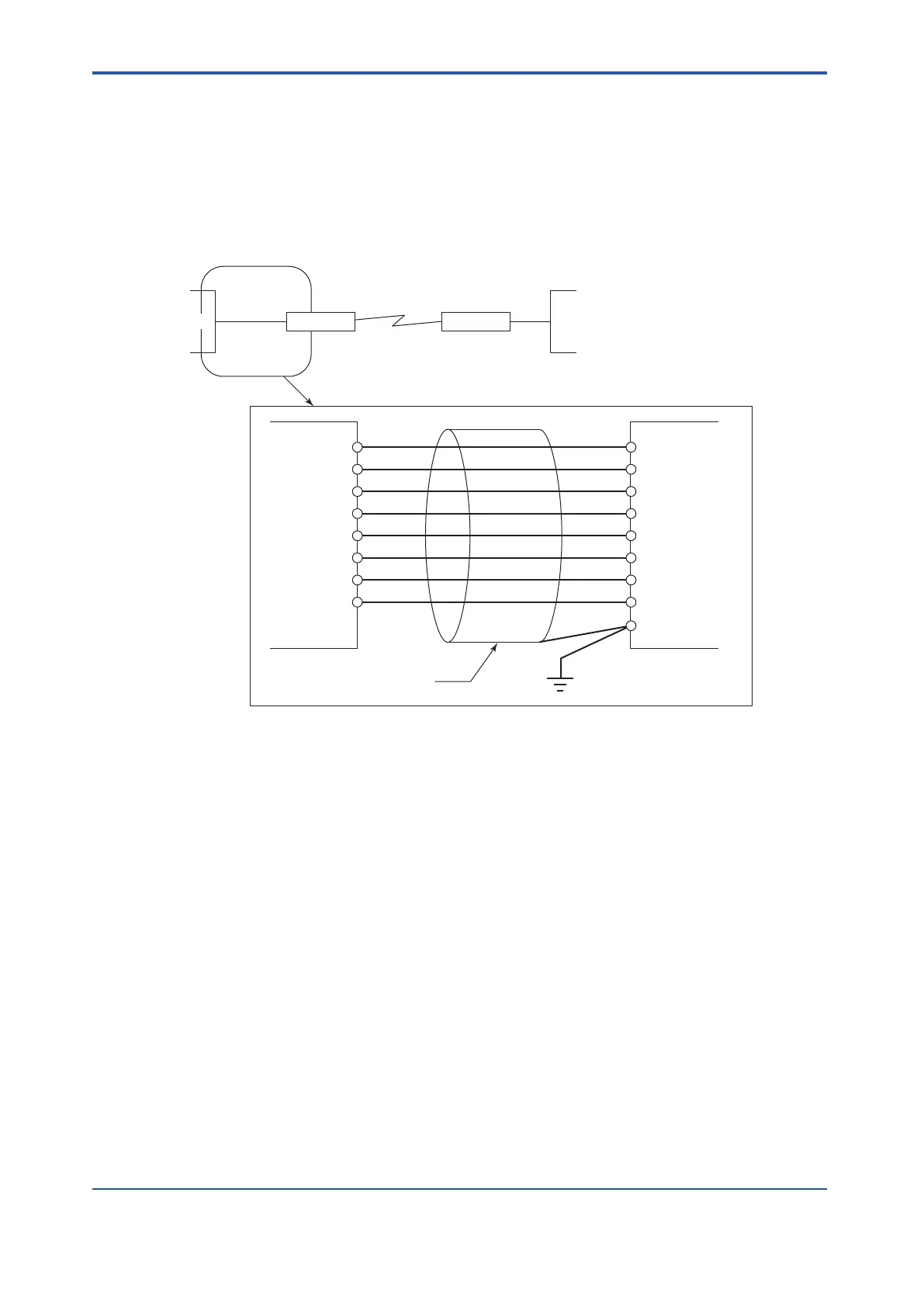
Connection with Modem
The following figure shows the cable between the ALR1
11 and the modem for communicating
with the external device.
The length of the cable for connecting ALR111 and the modem should be less than 15 me-
ters.
Protective grounding system
ALR111 Modem
1 FG
Sheathed cable
2 SD
3 RD
4 RS
5 CS
6 DR
20 ER
7 SG
8 CD
SD 3
RD 2
RS 7
CS 8
DR 6
ER 4
SG 5
CD 1
Modem
External device
RS-232C
Modem ALR111
Figure 5.5.1-2 Cable Connection when the ALR111 and the External Device are Connected Using Mo-
dems
l
Connecting to the External Device with RS-232C D-Sub 25-Pin Connector
(Direct Connection)
The following figure shows the cable between the ALR1
11 and a external device with
RS-232C D-Sub 25-Pin connector. This connection requires a 9-pin connector at one end of
the cable and a 25-pin connector at the other end.
The length of the cable for connecting ALR111 and the external device should be less than 15
meters.
<5.5 Connection of Communication Modules > 5-36
IM 32Q06C10-31E 4th Edition : Jan.30,2015-00
 Loading...
