l
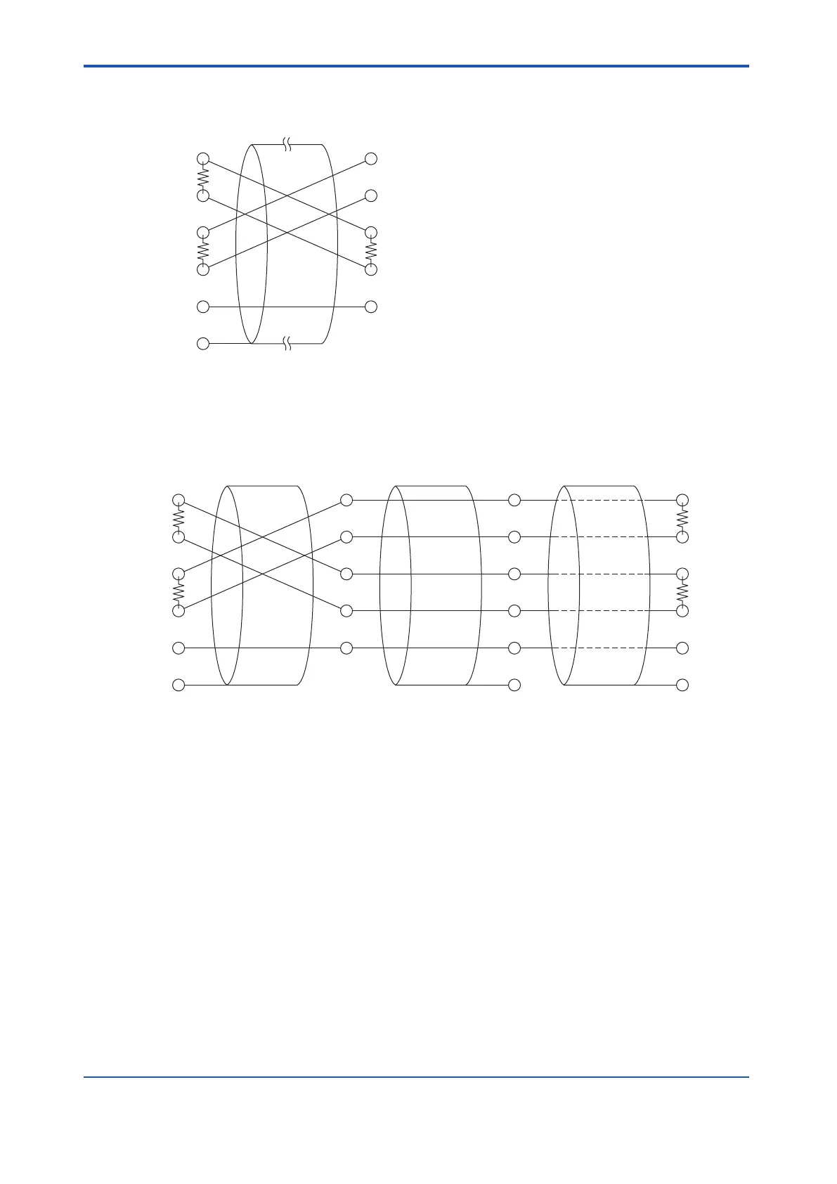
1 to 1 Connection in 4-wire T
ype
External device
TX+
TX-
RX+
RX-
SG
R2
R2
R1: Termination resistance of 120 ohm
R2: According to the instruction on the external device side
ALR121
TX+
TX-
RX+
RX-
SG
FG
R1
Figure 5.5.2-4 1 to 1 Connection in 4-wire Type
l
1 to n Connection in 4-wire T
ype
External device
TX+
TX-
RX+
RX-
SG
FG
TX+
TX-
RX+
RX-
SG
FG (*1)
TX+
TX-
RX+
RX-
SG
R2
R2
TX+
TX-
RX+
RX-
SG
FG (*1)
R1
R1
ALR121
R1: Termination resistance of 120 ohm
R2: According to the instruction on the external device side
*1: Connect to the grounding terminal(FG) of the unit where ALR121 installed
Figure 5.5.2-5 1 to n Connection in 4-wire Type
In the case that the ALR121 is a communication master
, both the four-wire type cable and
two-wire cable can be used for connecting ALR121 and the external device with either 1 to 1
or 1 to n connection.
In the case that the external device is a communication master, only the four-wire type cable
can be used.
<5.5 Connection of Communication Modules > 5-43
IM 32Q06C10-31E 4th Edition : Jan.30,2015-00
 Loading...
