Table 7.2.3-3 Setting of DIP Switches for Action Mode Setting (SW4)
Bit 6 OFF
Bit 5 FIX OFF
Bit 4 PORT OFF
Bit 3 OFF
Bit 2 DOMN OFF
Bit 1 STA OFF
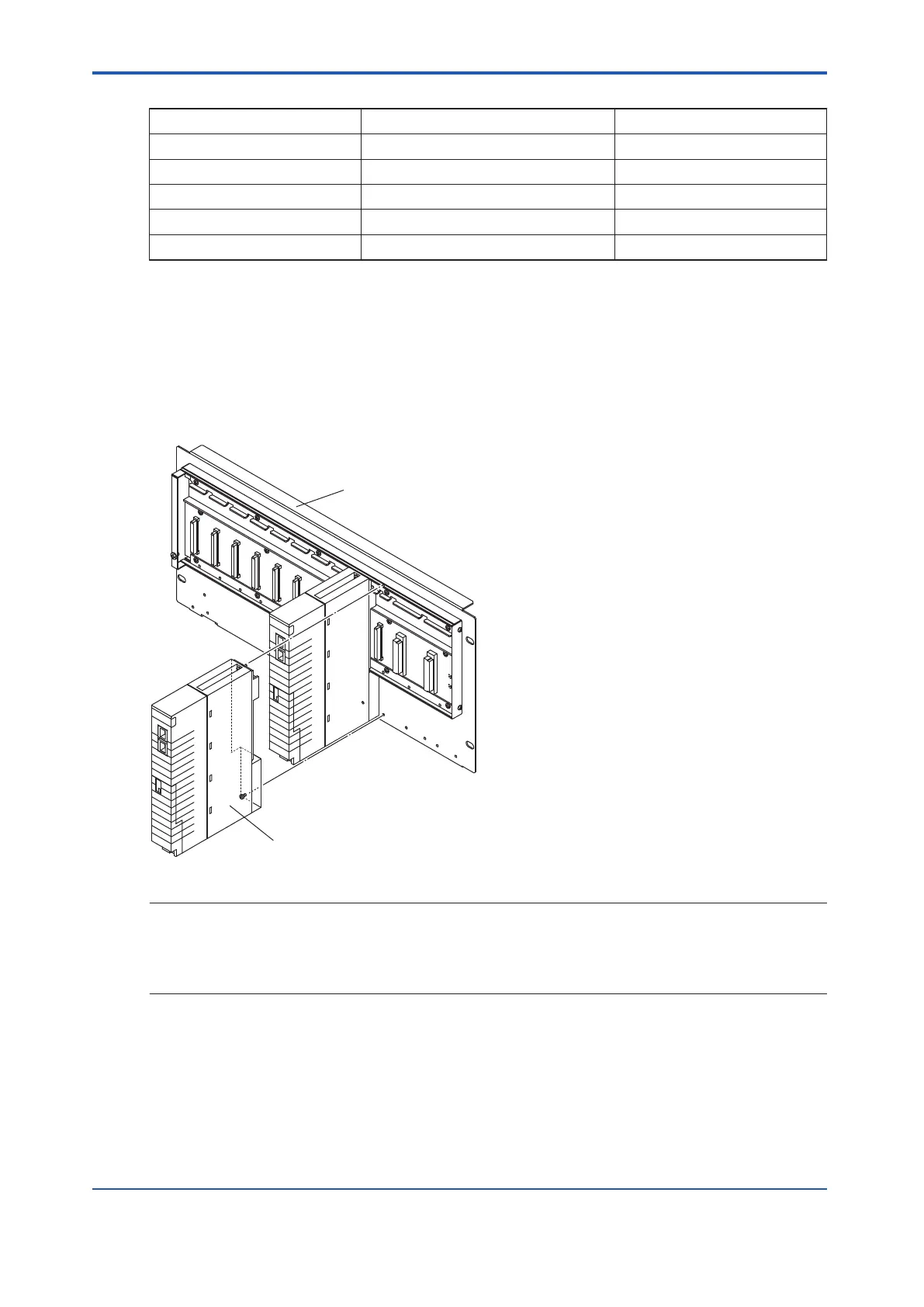
4. Without connecting the cables for BUS1 and BUS2, install the processor module to the
base unit.
5. Push the START/STOP switch on the processor module to stop the module, and make
sure that the HRDY LED is OFF.
6. Keep the processor module at this status for about a minute.
7. Remove the processor module from the base unit.
Base unit
Processor module
Figure 7.2.3-1 Replacing the Processor Module
SEE
ALSO
For more information about DIP switches, refer to:
•
“l SCP461” on page 4-4
•
“l SCP451” on page 4-4
<7.2 Replacing Common Modules > 7-13
IM 32Q06C10-31E 4th Edition : Jan.30,2015-00
 Loading...
