IM 05P01C31-15EN page 2/12
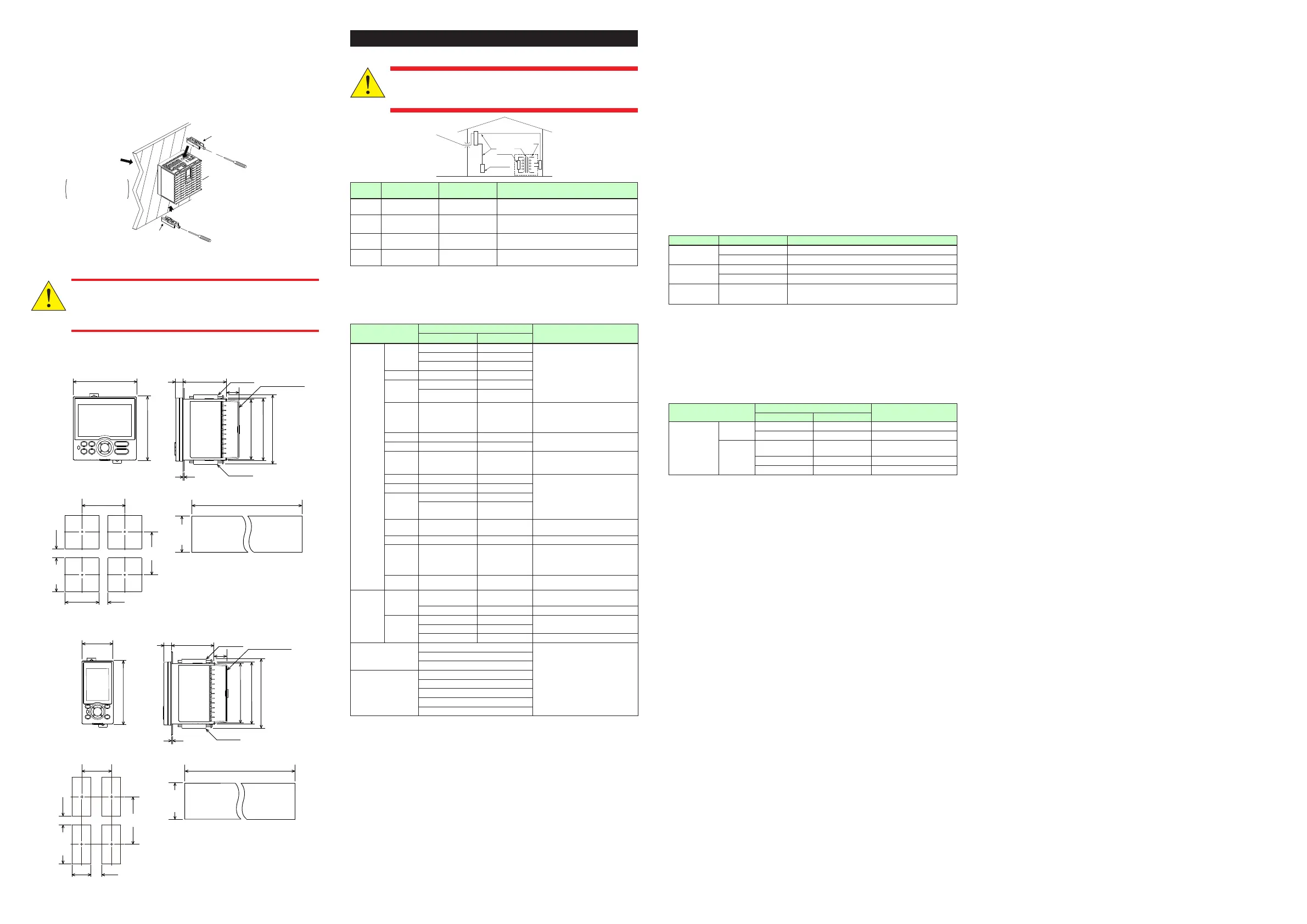
■ Mounting the Instrument Main Unit
Provideaninstrumentedpanelsteelsheetof1to10mmthickness.
Afteropeningthemountingholeonthepanel,followtheproceduresbelowtoinstall
thecontroller:
1) Insertthecontrollerintothe openingfromthefront ofthepanelsothat the
terminalboardontherearisatthefarside.
2)
Setthebracketsinplaceonthetopandbottomofthecontrollerasshowninthegure
below,thentightenthescrewsofthebrackets.Takecarenottoovertightenthem.
Bracket
(top mounting hardware)
Terminal board
Bracket
(bottom mounting hardware)
Panel
Insert a screwdriver into the
brackets to tighten the screws.
Direction to insert the
controller
Appropriate
tightening torque:
0.25 N•m
Insert the controller
into the opening at
the front of the panel.
•
Tighten the screws with appropriate tightening torque within 0.25 N•m.
Otherwise it may cause the case deformation or the bracket damage.
• Make sure that foreign materials do not enter the inside of the
instrument through the case’s slit holes.
■ External Dimensions and Panel Cutout Dimensions
(25)
(53) (2.09)
[(N-1)×96+92]
117 (4.61) min.
145 (5.71)
min.
+0.8
0
+0.8
0
92
“N” stands for the number of controllers to be
installed.
However, the measured value applies if N≥5.
65 (2.56)
20 (0.79)
11
(0.43)
1 to 10 mm (0.04 to 0.39 inch) (panel thickness)
Bracket
Bracket
94.6 (3.72)
91.6 (3.61)
105.2 (4.14)
96 (3.78)
96 (3.78)
• General mounting • Side-by-side close mounting
Terminal cover
Normal tolerance:
±(value of JIS B 0401-1998 tolerance class IT18)/2
+0.8
0
92
+0.03
0
(0.98)
+0.03
(3.62 )
+0.8
0
92
+0.03
0
(3.62 )
([(N-1)×3.78+3.62] )
+0.03
0
[(N-1)×48+45]
+0.6
0
65 (2.56)
48 (1.89)
11 (0.43)
1 to 10 mm (0.04 to 0.39 inch) (panel thickness)
Bracket
Bracket
Terminal cover
94.6 (3.72)
96 (3.78)
105.2 (4.14)
70 (2.76)
min.
(25)
145 (5.71)
min.
+0.6
0
45
(53) (2.09)
+0.8
0
92
• General mounting
• Side-by-side close mounting
20 (0.79)
91.6 (3.61)
“N” stands for the number of controllers to be
installed.
However, the measured value applies if N≥
Normal tolerance:
±(value of JIS B 0401-1998 tolerance class IT18)/2
+0.03
0
(3.62 )
+0.02
(1.77 )
(0.98)
+0.8
0
92
+0.03
0
(3.62 )
([(N-1)×1.89+1.77] )
+0.02
0
4. HardwareSpecications
This instrument is for Measurement Category No.1.
Do not use it for measurements in locations falling under Measure-
ment Categories No.2, No.3, and No.4.
Internal Wiring
Outlet
IV
III
T
O( I )
II
Category
IEC/EN/CSA/UL
61010-1
EN 61010-2-030 Remarks
No.1
Measurement
CategoryI
O(Other)
For measurements performed on circuits not direct-
lyconnectedtoMAINS.
No.2
Measurement
CategoryII
Measurement
CategoryII
For measurements performed on circuits directly
connectedtothelow-voltageinstallation.
No.3
Measurement
CategoryIII
Measurement
CategoryIII
Formeasurementsperformedinthebuildinginstal-
lation.
No.4
Measurement
CategoryIV
Measurement
CategoryIV
For measurements performed at the source of the
low-voltageinstallation.
■ InputSpecications
●UniversalInput(Equippedasstandard)
• Numberofinputs:1
• Inputtype,instrumentrange,andmeasurementaccuracy:Seethetablebelow,
Input Type
Instrument Range
Accuracy
ºC ºF
Thermo-
couple
K
-270.0to1370.0ºC -450.0to2500.0ºF ±0.1%ofinstrumentrange±1digitfor
0°Cormore
±0.2%ofinstrumentrange±1digitfor
lessthan0°C
±2%ofinstrumentrange±1digitfor
lessthan-200.0°CofthermocoupleK
±1%ofinstrumentrange±1digitfor
lessthan-200.0°CofthermocoupleT
-270.0to1000.0ºC -450.0to2300.0ºF
-200.0to500.0ºC -200.0to1000.0ºF
J -200.0to1200.0ºC -300.0to2300.0ºF
T
-270.0to400.0ºC -450.0to750.0ºF
0.0to400.0ºC -200.0to750.0ºF
B 0.0to1800.0ºC 32to3300ºF
±0.15%ofinstrumentrange±1digit
for400°Cormore
±5%ofinstrumentrange±1digitfor
lessthan400°C
S 0.0to1700.0ºC 32to3100ºF
±0.15%ofinstrumentrange±1digit
R 0.0to1700.0ºC 32to3100ºF
N -200.0to1300.0ºC -300.0to2400.0ºF
±0.1%ofinstrumentrange±1digit
±0.25%ofinstrumentrange±1digit
forlessthan0°C
E -270.0to1000.0ºC -450.0to1800.0ºF ±0.1%ofinstrumentrange±1digitfor
0°Cormore
±0.2%ofinstrumentrange±1digitfor
lessthan0°C
±1.5%ofinstrumentrange±1digitfor
lessthan-200.0°CofthermocoupleE.
L -200.0to900.0ºC -300.0to1600.0ºF
U
-200.0to400.0ºC -300.0to750.0ºF
0.0to400.0ºC -200.0to1000.0ºF
W 0.0to2300.0ºC 32to4200ºF
±0.2%ofinstrumentrange±1digit
(Note2)
Platinel 2 0.0to1390.0ºC 32.0to2500.0ºF ±0.1%ofinstrumentrange±1digit
PR20-40 0.0to1900.0ºC 32to3400ºF
±0.5%ofinstrumentrange±1digitfor
800°Cormore
Accuracyisnotguaranteedforless
than800°C.
W97Re3-
W75Re25
0.0to2000.0ºC 32to3600ºF ±0.2%ofinstrumentrange±1digit
RTD
JPt100
-200.0to500.0ºC -300.0to1000.0ºF
±0.1%ofinstrumentrange±1digit
(Note1)
-150.00to150.00ºC -200.0to300.0ºF ±0.1%ofinstrumentrange±1digit
Pt100
-200.0to850.0ºC -300.0to1560.0ºF
±0.1%ofinstrumentrange±1digit
(Note1)
-200.0to500.0ºC -300.0to1000.0ºF
-150.00to150.00ºC -200.0to300.0ºF ±0.1%ofinstrumentrange±1digit
Standardsignal
0.400to2.000V
±0.1%ofinstrumentrange±1digit
1.000to5.000V
4.00to20.00mA
DCvoltage/current
0.000to2.000V
0.00to10.00V
0.00to20.00mA
-10.00to20.00mV
0.0to100.0mV
Theaccuracyisthatinthestandardoperatingconditions:23±2°C,55±10%RH,andpowerfrequencyat50/60Hz.
Note1:±0.3°C±1digitintherangebetween0and100°C,±0.5°C±1digitintherangebetween-100and200°C.
Note2:W:W-5%Re/W-26%Re(HoskinsMfg.Co.).ASTME988
• Inputsampling(control)period:Selectfrom50,100,and200ms
• Burnoutdetection:
FunctionsatTC,RTD,andstandardsignal.
Upscale,downscale,andoffcanbespecied.
Forstandardsignal,burnoutisdeterminedto haveoccurredifitis0.1Vor 0.4
mAorless.
• Inputbiascurrent:0.05µA(forTCorRTD)
• Measuredcurrent(RTD):About0.16mA
• Inputresistance:
TCormVinput:1MΩormore
Vinput:About1MΩ
mAinput:About250Ω
• Allowablesignalsourceresistance:
TCormVinput:250Ωorless
Effectsofsignalsourceresistance:0.1µV/Ωorless
DCvoltageinput:2kΩorless
Effectsofsignalsourceresistance:About0.01%/100Ω
• Allowablewiringresistance:
RTDinput:Max.150Ω/wire(Theconductorresistancebetweenthethreewires
shallbeequal.)
Wiringresistanceeffect:±0.1ºC/10Ω
• Allowableinputvoltage/current:
TC,mV,mAandRTDinput:±10VDC
Vinput:±20VDC
mAinput:±40mA
• Noiserejectionratio:
Normalmode:40dBormore(at50/60Hz)
Commonmode:120dBormore(at50/60Hz)
For100-240VAC,thepowerfrequencycanbesetmanually.Automaticdetection
isalsoavailable.
For24VAC/DC,thepowerfrequencycanbesetmanually.
• Referencejunctioncompensationerror:
±1.0ºC(15to35ºC),±1.5ºC(-10to15ºCand35to50ºC)
• Applicablestandards:JIS/IEC/DIN(ITS-90)forTCandRTD
●AuxiliaryAnalogInput
•
Use:Remotesetpointsetting,externalcompensatinginput,auxiliaryinputforcomputation,etc.
• Numberofinputs:SeethetableofModelandSufxCodes.
• Inputtype,instrumentrange,andmeasurementaccuracy:Seethetablebelow.
Input Type Instrument Range Accuracy
Standardsignal
0.400to2.000V ±0.2%ofinstrumentrange±1digit
1.000to5.000V ±0.1%ofinstrumentrange±1digit
DCvoltage
0.000to2.000V ±0.2%ofinstrumentrange±1digit
0.00to10.00V ±0.1%ofinstrumentrange±1digit
DCvoltage
forhigh-input
impedance
0.000to1.250V ±0.1%ofinstrumentrange±1digit
• Inputsampling(control)period:Sameasthestandard-equippeduniversalinput
• Inputresistance:About1MΩ
However,10MΩormoreforDCvoltageforhigh-inputimpedancerange.
•Burnoutdetection:Functionsatstandardsignal
Burnoutisdeterminedtohaveoccurredifitis0.1Vorless.
●UniversalInput(Optioncode:/U1)
• Numberofinputs:SeethetableofModelandSufxCodes.
• Inputtype,instrumentrange,andmeasurementaccuracy:Sameasthestandard-
equippeduniversalinputexceptthetablebelow.
Input Type
Instrument Range
Accuracy
°C °F
4-wireRTD
JPt100
-200.0to500.0°C -300.0to1000.0°F ±0.5°C±1digit
-150.00to150.00°C -200.0to300.0°F ±0.2°C±1digit
Pt100
-200.0to850.0°C -300.0to1560.0°F
±0.1%ofinstrumentrange±1
digit(Note1)
-200.0to500.0°C -300.0to1000.0°F ±0.5°C±1digit
-150.00to150.00°C -200.0to300.0°F ±0.2°C±1digit
Note1
:±0.5°C±1digitintherangebetween-200.0and500.0°C/-300.0and1000.0°F.
• Inputsampling(control)period:Sameasthestandard-equippeduniversalinput.
• Burnoutdetection:Sameasthestandard-equippeduniversalinput.
■ ContactInputSpecications
• Numberofinputs:SeethetableofModelandSufxCodes.
• Inputtype:No-voltagecontactinputortransistorcontactinput
• Inputcontactrating:12VDC,10mAormore
Useacontactwithaminimumon-currentof1mAorless.
• ON/OFFdetection:
No-voltagecontactinput:
Contactresistanceof1kΩorlessisdeterminedas“ON”andcontact
resistanceof50kΩormoreas“OFF.”
Transistorcontactinput:
Inputvoltageof2Vorlessisdeterminedas“ON”andleakagecurrentmustnot
exceed100µAwhen“OFF.”
• Minimumstatusdetectionholdtime:Controlperiod+50ms
• Use:SPswitch,operationmodeswitch,andeventinput
■ AnalogOutputSpecications
• Numberofoutputs:
Controloutput:1
Cooling-sidecontroloutputofHeating/coolingtype:1
• Outputtype:Currentoutputorvoltagepulseoutput
• Currentoutput:4to20mADCor0to20mADC/loadresistanceof600Ωorless
• Currentoutputaccuracy:±0.1%ofspan(±5%ofspanfor1mAorless)
Theaccuracyisthat inthestandardoperating conditions:23±2°C,55±10%RH,
andpowerfrequencyat50/60Hz.
• Voltagepulseoutput:
Use:Timeproportionaloutput
On-voltage:12Vormore/loadresistanceof600Ωormore
Off-voltage:0.1VDCorless
Timeresolution:10msor0.1%ofoutput,whicheverislarger
■ RetransmissionOutputSpecications
• Numberofoutputs:Retransmissionoutput;1,sharedwith15VDClooppowersupply.
• Currentoutput:4to20mADCor0to20mADC/loadresistanceof600Ωorless
• Currentoutputaccuracy(conversion accuracyfromPV displayontheset scale):
±0.1%ofspan(±5%ofspanfor1mAorless)
Theaccuracyisthatinthestandardoperatingconditions:23±2°C,55±10%RH,
andpowerfrequencyat50/60Hz.
Thisisnotconversionaccuracy throughinputandoutput buttheperformanceof
transmission output itself.
■ 15VDCLoopPowerSupplySpecications
(Sharedwithretransmissionoutput)
• Powersupply:14.5to18.0VDC
• Maximumsupplycurrent:About21mA(withshort-circuitcurrentlimitingcircuit)
■ StepResponseTimeSpecications
Within500ms(whenthecontrolperiodis50msor100ms)
Within1s(whenthecontrolperiodis200ms)
(63%ofanalogoutputresponsetimewhenastepchangeof10to90%ofinputspanisapplied)
■ RelayContactOutputSpecications
• Contacttypeandnumberofoutputs:
Controloutput:contactpoint1c;1point
Cooling-sidecontroloutputofHeating/cooling type:contactpoint1c;1 point
(forUT55Aonly)
ForUT52A,contactpoint1a;2pointsforbothheatingandcoolingsides
Alarmoutput:contactpoint1a;3points(commonisindependent)
• Contactrating:
Contactpoint1c(controloutput):250VAC,3Aor30VDC,3A(resistanceload)
Contactpoint1a(controloutput):240VAC,3Aor30VDC,3A(resistanceload)
(forUT52Aonly)
Contactpoint1a(alarmoutput):240VAC,1Aor30VDC,1A(resistanceload)
• Use:Timeproportionaloutput,alarmoutput,FAILoutput,etc.
• Timeresolutionofcontroloutput:10msor0.1%ofoutput,whicheverislarger
Note:Thecontroloutputshouldalwaysbeusedwithaloadof10mAormore.
Thealarmoutputshouldalwaysbeusedwithaloadof1mAormore.
■ TriacOutputSpecications
• Contacttypeandnumberofoutput:zerocross;1point
Loadvoltage:75to250VAC
Allowableloadcurrent:0.8Awhentheambienttemperatureis20°C,0.3Awhenthe
ambienttemperatureis50°C.
• Minimumloadcurrent:20mA(*)
*:Ifthereisariskofsurgecurrent,connectacurrent-limitingreactor,acurrent-limitingfuseora
breakerinseriestotheloadpowersupply.
• Use:Timeproportionaloutput,Alarmoutput
• Time resolutionofcontroloutput:1/commercialfrequency(s) or0.1%ofoutput,
whicheverislarger.
■ TransistorContactOutputSpecications
• Numberofoutputs:SeethetableofModelandSufxCodes.
• Outputtype:Opencollector(SINKcurrent)
• Outputcontactrating:Max.24VDC,50mA
• Outputtimeresolution:Min.50ms
• Use:Alarmoutput,FAILoutput,etc.
■ PositionProportionalOutputSpecications
• Positionsignalinput:
Slideresistance:100Ωto2.5kΩoftotalresistance
100%sideandslideline:withdisconnectiondetection
0%side:withoutdisconnectiondetection
Currentinput:4to20mA(withdisconnectiondetection)
• Samplingperiod:50ms
• Measurementresolution:0.1%ofinputspan
• Positionproportionalrelayoutput:
UT55A:contactpoint1a;2points,250VAC,3Aor30VDC,3A(resistanceload)
UT52A:contactpoint1a;2points,240VAC,3Aor30VDC,3A(resistanceload)
Note:Thisshouldalwaysbeusedwithaloadof10mAormore.
■ HeaterBreakAlarmSpecications
• Numberofinputs:2
• Numberofoutputs:2(transistorcontactoutput)
• Use:Measurestheheatercurrentusinganexternalcurrenttransformer(CT)and
generatesaheaterbreak alarmwhenthemeasuredvalue islessthanthe break
detectionvalue.
• Currenttransformerinputresistance:About9.4Ω
•
Currenttransformerinputrange:0.0to0.1Arms(0.12Armsormorecannotbeapplied.)
• Heatercurrentsettingrange:OFF,0.1to300.0Arms
Heatercurrentmeasuredvaluedisplayrange:0.0to360.0Arms
Note:TheCTratiocanbeset.CTratiosettingrange:1to3300
• RecommendedCT:CTfromU.R.D.,Ltd.
CTL-6-S-H:CTratio800,measurablecurrentrange:0.1to80.0Arms
CTL-12L-30:CTratio3000,measurablecurrentrange:0.1to180.0Arms
• Heatercurrentmeasurementperiod:200ms
• Heatercurrent measurementaccuracy:±5% ofcurrenttransformer inputrange
span±1digit(CTerrorisnotincluded.)
•
Heatercurrentdetectionresolution:Within1/250ofcurrenttransformerinputrangespan
• BreakdetectionOn-time:Min.0.2second(fortimeproportionaloutput)
■ 24VDCLoopPowerSupplySpecications
• Use:Powerissuppliedtoa2-wiretransmitter.
• Powersupply:21.6to28.0VDC
• Ratedcurrent:4to20mADC
• Maximumsupplycurrent:About30mA(withshort-circuitcurrentlimitingcircuit.)
■ SafetyandEMCStandards
• Safety:
CompliantwithIEC/EN61010-1(CE),IEC/EN61010-2-201(CE),IEC/EN61010-2-030
(CE),approvedbyCAN/CSAC22.2No.61010-1(CSA),approvedbyUL61010-1.
Installationcategory:II
Pollutiondegree:2
Measurementcategory:I(CATI)(UL,CSA)
O(Other)(CE)

 Loading...