IM 05P01C31-15EN page 8/12
7.
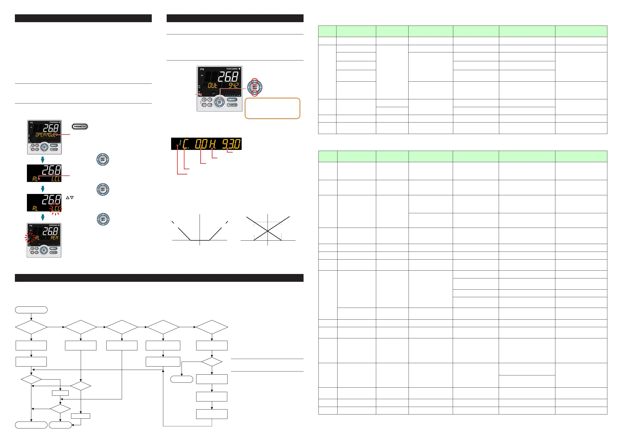
Switching between REM (Remote) and LCL (Local)
Remoteandlocalswitchingcanbeperformedusinganyofthefollowing:
(1)Contactinput,(2)Parameter,(3)Communication,and(4)Userfunctionkey.
LCL (Local)
Controlisperformedusingthetargetsetpointsetonthecontroller.
REM (Remote)
Controlisperformedusinganexternalanalogsignalthatisusedasthetargetset-
point.Thefollowingshowsan exampleofswitchingfromlocalto remoteusingthe
parameter.
Fordetailsofotherswitchingmethods,seeUser’sManual(IM05P01C31-01EN).
•ThePIDgroupforthelocalSPnumberisusedasPIDinremotemode.
NOTE
WhenthecontactinputisON,operationcannotbeperformedusingtheparameter,
communication,orkey. Whenthecontactinput isOFFandthe settingisswitched
usingtheparameter,communication,orkey, thelastswitchingoperationis per-
formed.
Show the Operation Display.
Hold down the PARAMETER key or PARA key
for 3 seconds to display MODE menu.
Press the SET/ENTER key.
Press the SET/ENTER key.
The REM lamp is lit.
Change the operation mode using
the Up/Down arrow keys.
Blinks during the change.
Press the SET/ENTER key.
The parameter R.L (REMOTE/LOCAL switch)
is displayed.
8.
Manipulating Control Output in Manual Mode
NOTE
Inmanualmode,controloutput ismanipulatedbyoperatingthekeys (thevalueis
changedusingtheUp/Downarrowkeys,thenoutputtedasitis).
EveniftheSET/ENTER keyisnotpressed, thecontroloutputvalue changesac-
cordingtothedisplayedvalue.
Instopmode(whentheSTOPlampislit),controloutputcannotbemanipulated.
MAN lamp is lit.
Up arrow key: increases control output.
Down arrow key: decreases control output.
In Position proportional control:
Up arrow key; opens the valve.
Down arrow key; closes the valve.
Output; only while pressing a key.
OUT; valve opening (0-100%)
Output manipulation in Position proportional control
is not restricted from output limiters (OH, OL).
Manual operation in Heating/cooling control
Symbol of cooling side
Target setpoint (SP) number
Symbol of heating side
Heating-side control output
Cooling-side control output
Uparrowkey:concurrently decreasescooling-sidecontroloutput andincreases
heating-sidecontroloutput.
Downarrowkey:concurrentlyincreasescooling-sidecontroloutput anddecreases
heating-sidecontroloutput.
(Eithernoneoftheheating-sideand cooling-sideoutputsarepresented,orboth of
themarepresentedaccordingtothedeadbandsetting.)
DB=24.8
Dead band: Operation parameter DB
Control computation output Control computation output
12.40-12.4
Manipulated output change
when a dead band is positive (+)
Actual output (%)
100
DB= -24.8
12.40-12.4
Manipulated output change
when a dead band is negative (-)
100
Cooling-side
manipulated output
Heating-side
Heating-side
manipulated output
Cooling-side
9. Troubleshooting
■TroubleshootingFlow
IftheOperationDisplaydoesnotappearafterturningonthecontroller’spower,checktheproceduresinthefollowingowchart.
Ifaproblemappearstobecomplicated,contactoursalesrepresentatives.
defective?
Contact us for repair.
Problem solved.
No communication
capability
Completely
inactive?
Yes
Yes
Yes
No
No
No
Key
operation
failure?
Yes
No
Yes
Check wiring of the
power terminals.
Check the key lock
setting.
Display
failure?
*
Yes
No
Turn off power, and
then turn it on again.
I/O signal
failure?
Yes
No
Check the
supply voltage.
Check the
specifications and polarity
of connected devices .
Check the communication-
related parameters.
Check the specifications
of communication
devices.
Check the
communication wiring.
Communication
failure?
No
With
communi-
cation?
Yes
Yes
Normal?
Is the
key locked?
Check the specifications
of the controller.
Yes
No
Correct?
Correct the error(s).
Cancel the setting.
Check the I/O specifications
of the controller.
* The LCD (a liquid crystal display) is used for
a display portion of this product.
The LCD has a characteristic that the display action
becomes late at the low temperature.
Additionally, the luminance and contrast degradation
are caused due to aged deterioration.
However, the control function is not affected.
■
Remedies if Power Failure Occurs
during Operations
• Instantaneouspowerfailurewithin20ms.
Apowerfailureisnotdetected. Normal
operation continues.
• Powerfailureforlessthanabout5seconds,
orforabout5secondsormore.
Affectsthe"settings"and"operationsta-
tus."
Fordetails,seeUser's Manual(IM
05P01C31-01EN).
NOTE
Writedownthesettingsof parametersfora
repairrequest.
n
Errors at Power On
Theerrorsshownbelowmayoccurinthefaultdiagnosiswhenthepoweristurnedon.(FordetailsofSetpointdisplayandinput/outputactionwheneacherroroccurs,seeUser’sManual(IM05P01C31-01EN).
PV display
(Operation
Display)
Setpoint display
(Operation Display)
Status indicator
(Operation Display)
Parameter that displays error
details
Error description Cause and diagnosis Remedy
Indication off Indication off — — FaultyMCURAM/MCUROM MCURAM/MCUROMarefailed. Faulty.Contactusforrepair.
ERR
SYS-----
—
— System data error System data is corrupted. Faulty.Contactusforrepair.
PAR0004
(foruserdefaultvalueerroronly)
Setupparameter(PA.ER)
User(parameter)defaultvalueerror
Userparameteriscorrupted.
Initializedtofactorydefaultvalue.
Checkandreconguretheinitialized
settingparameters.Errorindicationis
erased when the power is turned on
again.
PAR0010
(forsetupparametererroronly)
Setup parameter error
Setup parameter data is corrupted.
Initializedtouserdefaultvalue.
PAR0020
(foroperationparametererror
only)
Operationparametererror
Operationparameterdataiscorrupted.
Initializedtouserdefaultvalue.
SLOT0017
(0017:Erroroccurstoall
hardwareofE1toE4-terminal
areas.)
Setupparameter(OP.ER)
Nonrespondinghardwareof
extendedfunction(E1toE4-
terminalareas)
Inconsistence of system data and
hardwareofextendedfunction.
Nonrespondingcommunicationbetween
hardwareofextendedfunction(E1toE4-
terminalareas).
Faulty.
Contactusforrepair.
Normal
indication
Normalindication
Rightmostdecimalpoint
onPVdisplayblinks.
Setupparameter(PA.ER)
Calibrationvalueerror
Initializedtocalibrateddefaultvaluebecause
ofcorruptedfactorydefaultvalue.
Faulty.Contactusforrepair.
Rightmostdecimalpoint
onSymboldisplayblinks.
FaultyFRAM
Datawriting(storing)toFRAMis
impossible.
Normal
indication
Normalindication LADDERlampblinks Setupparameter(LA.ER) Corruptedladderprogram
Ladderprogramiscorrupted.
Operateswithoutladderprogram.
Downloadtheladderprogramagain.
Normal
indication
0.00000000
(Decimalpointontheleftof
theSymboldisplayblinks)
— Setupparameter(OP.ER) Userproleerror Userproleiscorrupted. Downloadtheuserproleagain.
n
Errors during Operation
Theerrorsshownbelowmayoccurduringoperation.(Forinput/outputactionwheneacherroroccurs,seeUser’sManual(IM05P01C31-01EN).
PV display
(Operation
Display)
Setpoint display
(Operation Display)
Status indicator
(Operation Display)
Parameter that displays
error details
Error description Cause and diagnosis Remedy
AD.ERR
Normalindication(Note) — Setupparameter(AD1.E)
AnaloginputterminalADCerror
•PVinput
•RSPinput(E1-terminalarea)
•AIN2input(E2-terminalarea)
•AIN4input(E4-terminalarea)
AnaloginputterminalADvalueerror
Faulty.
Contactusforrepair.
RJC.E
(DisplaysRJC.
EandPV
alternately.)
Normalindication(Note) — Setupparameter(AD1.E)
UniversalinputterminalRJCerror
•PVinput
•RSPinput(E1-terminalarea)
UniversalinputterminalRJCerror
Faulty.
Contactusforrepair.
SettheparameterRJCtoOFFtoerase
error indication.
B.OUT
Normalindication(Note) —
Setupparameter(AD1.E)
Analoginputterminalburnouterror
•PVinput
•RSPinput(E1-terminalarea)
•AIN2input(E2-terminalarea)
•AIN4input(E4-terminalarea)
Analoginputterminalsensorburnout
Checkwiringandsensor.
Errorindicationiserasedinnormal
operation.
Setupparameter(PV1.E/PV2.E)
PVinputburnouterror(Loop1,
Loop2)
BurnoutofanaloginputconnectedtoPV
Checkwiringandsensorofconnected
analoginputterminals.
Errorindicationiserasedinnormal
operation.
OVER
-OVER
Normalindication — Setupparameter(PV1.E/PV2.E)
PVinputover-scale
PVinputunder-scale
(PVvaluesoutof-5to105%)(Loop
1,Loop2)
PVinputisoutof-5to105%.Alsooccurs
whenthedataoutofrangewhichisthe
ladder calculation result is input.
Checkanaloginputvalueorladder
program.
Normal
indication
Normalindication — Setupparameter(PV1.E/PV2.E)
RSPinputburnouterror(Loop1,
Loop2)
BurnoutofanaloginputconnectedtoRSP
Checkwiringandsensor.Error
indication is erased in normal operation.
Normal
indication
RSPB.OUT
— Setupparameter(PV1.E/PV2.E)
BurnouterrorwhenRSPinputis
usedforcontrol(Loop1,Loop2)
BurnoutofanaloginputconnectedtoRSP
whenRSPisusedforcontrolcomputation
Checkwiringandsensor.Error
indication is erased in normal operation.
Normal
indication
OUT-----
— Setupparameter(AD2.E)
Feedbackinputresistor/current
burnout
Feedbackinputburnout
Checkwiringoffeedbackinputresistor/
current.Errorindicationiserasedin
normal operation.
Normal
indication
Normalindication LADDERlampblinks Setupparameter(LA.ER)
Laddercalculationoverow
Floatingpointcomputationforladder
calculationisinnite.
Checktheladderprogram.
Loadfactorover100%
Computationdoesnotendwithinthe
controlperiod(loadfactoris100%or
more).
Changethecontrolperiodorreduce
thenumberofstepsfortheladder
program.
Loadfactorover200%
(Forcedend)
Computationdoesnotendwithinthecontrol
period(loadfactoris200%ormore).
Changethecontrolperiodorreducethe
numberofstepsfortheladderprogram.
Ladderprogramerror Ladderprogramiscorrupted.
Downloadtheladderprogramagain.If
theerrorindicationisstillnoterased,
thereisafault.Contactusforrepair.
0.00000000
(Decimalpointontheleftof
theSymboldisplayblinks)
— Setupparameter(OP.ER) Peer-to-peercommunicationerror Peer-to-peercommunicationerror
Checkthatthetargetdevicesare
connected correctly.
Recoveryatnormalreceipt.
AT.E
Normalindication — Setupparameter(PV1.E/PV2.E)
Auto-tuningtime-out
(Loop1,Loop2)
Auto-tuningdoesnotendevenwhen24
hourshaveelapsedafterthestartoftuning.
Checktheprocess.Holddownanykeyto
erase the error indication
VAT.E
Normalindication — Setupparameter(AD2.E)
Valvepositionautomatic
adjustmenterror
Fully-closedvalvepositionisequaltoorlarger
thanthefully-openvalvepositionafterautomatic
valvepositionadjustmentisperformed.
Checkwiringandvalve.Holddownany
key to erase the error indication.
Normal
indication
0.00000000
(Decimalpointontheleftof
theSymboldisplayblinks)
— Setupparameter(OP.ER)
Communicationerror
(RS-485communication)
Framingparityerror
Bufferoverow
Inter-charactertime-out
Checksumerror(PClinkcommunicationwith
checksum)
CRCcheckerror(Modbus/RTU)
LRCcheckerror(Modbus/ASCII)
Checkthecommunicationparameters.
Recoveryatnormalreceipt.
Holddownanykeytostopblinking.
Normal
indication
0.00000000
(Decimalpointontheleftof
theSymboldisplayblinks)
— Setupparameter(OP.ER)
Communicationerror
(coordinatedoperation)
Inconsistenceofloopbetweencoordinated
masterandslaves
Checkthecommunicationparameters.
Recoveryatnormalreceipt.
Changefromremotetolocalmodetostop
blinking.
Whenthemodeischangedfromremoteto
local,SPtrackingdoesnotworkevenifitis
settoON.
Communicationfromcoordinatedmasteris
interrupted for 2 seconds.
Normal
indication
0.00000000
(Decimalpointontheleftof
theSymboldisplayblinks)
— Setupparameter(OP.ER) Userproleerror Userproleiscorrupted. Downloadtheuserproleagain.
Normal
indication
Normalindication
Rightmostdecimalpointon
Symboldisplayblinks.
Setupparameter(PA.ER) FaultyFRAM
Writing(storing)datatoFRAMisimpossible.
Faulty.Contactusforrepair.
Undened Undened — —
FaultyMCU/DCU
(ROM/RAMerror,corrupted)
MCU/DCUiscorrupted. Faulty.Contactusforrepair.
Note:WhenanerroroccursininputshowninAnaloginputdisplay(Operationdisplay),SetpointdisplayshowsthesamesymbolasthePVdisplay.

 Loading...


