IM 05P01C31-15EN page 5/12
Contents
1. NamesandFunctionsofDisplayParts
2. Setup Procedure
3. QuickSettingFunction(SettingofInputandOutput)
4.
AdjustingValvePositionAutomatically(foraPositionProportionalTypeControllerOnly)
5. SettingAlarmType
6. SettingAlarmSetpoint
1. Names and Functions of Display Parts
(2) + (3) + (4) : Setpoint display
(1)
(9)
(2)
(10)
(11)
(12)
(13)
(4)
(8)
(11)
(10)
(13)
(3)
(5)
(6)
(7)
(8)
(2)
(3)
(4)
(5)
(6)
(12)
No.ingure Name Description
(1)
PVdisplay
(whiteorred)
DisplaysPV.
Displaysanerrorcodeifanerroroccurs.
DisplaysthescrollingguideintheMenuDisplayandParameter
SettingDisplaywhentheguidedisplayON/OFFissettoON.
(2) Groupdisplay(green)
Displaysagroupnumber(1to8orR)andterminalarea(E1toE4).
1to8representSPnumbersintheOperationDisplay.
RandE1toE4aredisplayedintheParameterSettingDisplay.
(3)
Symboldisplay(orange)
Displaysaparametersymbol.
(4) Datadisplay(orange) Displaysaparametersetpointandmenusymbol.
(5)
Bar-graphdisplay
(orangeandwhite)
Displayscontroloutputvalue(OUT)andmeasuredinputvalue(PV).
Thedatatobedisplayedcanbesetbytheparameter.
Initialvalue:upperbar(deviation),lowerbar(controloutput,
internalcomputedvalueinPositionproportionalcontrol);
inHeating/coolingcontrol,upperbar(heating-sidecontroloutput),
lowerbar(cooling-sidecontroloutput)
(6)
Eventindicator
(orange)
UT55A:Litwhenthealarms1to8occur.(Initialvalue:1to4)
UT52A:Litwhenthealarms1to4occur.
Eventdisplaysotherthanalarmscanbesetbytheparameter.
(7)
Keynavigationindica-
tor(green)
LitorblinkswhentheUp/DownorLeft/Rightarrowkeyoperation
ispossible.
(8)
Parameterdisplaylevel
indicator(green)
Displaysthesettingconditionsoftheparameterdisplaylevelfunction.
Parameter display level EASY PRO
Easysettingmode Lit Unlit
Standardsettingmode Unlit Unlit
Professionalsettingmode Unlit Lit
(9)
Deviationindicator
(forUT55Aonly)
(green)
Displaysthestatusofadeviation(PV-SP).
:Litifadeviationexceedsthedeviationdisplayband.
:Litwhenadeviationiswithinthedeviationdisplayband
:Litifadeviationfallsbelowthedeviationdisplayband.
ThedeviationindicatorisunlitiftheDisplaysotherthantheOp-
erationDisplayorSELECTDisplayareshown.Deviationdisplay
bandcanbesetbytheparameter.
(10)
Status indicator
(greenandred)
Displaystheoperatingconditionsandcontrolstatus.
Indicator Description
REM Litwheninremotemode(REM).
CAS Litwhenincascademode(CAS).
PRG Unused
STOP Litwheninstopmode(STOP).
MAN
Litwheninmanualmode(MAN).
Blinksduringauto-tuning.
(11) Securityindicator(red) Litifapasswordisset.Thesetupparametersettingsarelocked.
(12)
Ladderoperation
indicator(green)
Litwhiletheladderoperationisexecuted.
(13)
Loop2indicator
(LP2lamp)
(green)
LitwhenthecontrolmodeisCascadecontrol.
IntheOperationDisplay,theLP2lampislitwhiletheLoop-2data
is displayed on Setpoint display.
IntheParameterSettingDisplay,theLP2lampindicatestheloop
ofdisplayedmenusymbolorparametersymbol.TheLP2lampislit
whiletheLoop-2menusymbolorparametersymbolisdisplayed.
(4)
(5)
(1)
(2)
(4)
(5)
(6)
(1)
(2)
No.ingure Name Description
(1)
UT55A:DISPLAYkey
UT52A:DISPkey
UsedtoswitchtheOperationDisplays.
PressthekeyintheOperationDisplaytoswitchtheprovided
OperationDisplays.
PressthekeyintheMenuDisplayorParameterSettingDisplay
toreturntotheOperationDisplay.
(2)
UT55A:
PARAMETERkey
UT52A:PARAkey
Holddownthekeyfor3secondstomovetotheOperation
ParameterSettingDisplay.
HolddownthekeyandtheLeftarrowkeysimultaneouslyfor3
secondstomovetotheSetupParameterSettingDisplay.
PressthekeyintheParameterSettingDisplaytoreturntothe
MenuDisplay.Pressthekeyoncetocanceltheparameterset-
ting(setpointisblinking).
(3)
SET/ENTERkey
Up/Down/Left/Right
arrow keys
SET/ENTERkey
PressthekeyintheMenuDisplaytomovetotheParameter
SettingDisplayoftheMenu.PressthekeyintheParameter
SettingDisplaytotransfertotheparametersettingmode
(setpointisblinking),andtheparametercanbechanged.
Pressthekeyduringparametersettingmodetoregisterthe
setpoint.
Up/Down/Left/Rightarrowkeys
PresstheLeft/RightarrowkeysintheMenuDisplaytoswitch
theDisplays.
PresstheUp/Down/Left/RightarrowkeysintheParameter
SettingDisplaytoswitchtheDisplays.
PresstheUp/Downarrowkeysduringparametersettingmode
(setpointisblinking)tochangeasetpoint.
PresstheLeft/Rightarrowkeysduringparametersettingmode
(setpointisblinking)tomovebetweendigitsaccordingtotheparameter.
(4) Light-loaderinterface
Itisthecommunicationinterfacefortheadaptercableusedwhen
settingandstoringparametersfromaPC.TheLL50AParameter
SettingSoftware(soldseparately)isrequired.
(5) A/Mkey
UsedtoswitchbetweenAUTOandMANmodes.
ThesettingisswitchedbetweenAUTOandMANeachtimethe
key is pressed.
(6) Userfunctionkeys
TheUT55AhasF1,F2,andFnkeys.
TheUT52AhasonlytheFnkey.Theusercanassignafunction
tothekey.Thefunctionissetbytheparameter.
Note: Thecommunicationconnector(maintenanceport)forLL50AParameterSettingSoftwareis
on the top of the unit.
2. Setup Procedure
ThefollowingowchartshowsthesetupprocedureforUT55AandUT52A.
Install and wire a controller.
Monitoring and control of regular operations
Adjust PID using auto-tuning or manually for PID control.
Other setup
Operation
NO
NO NO
YES
YES YES
Control mode: Single-loop control only
Set the other parameters as needed.
PID tuning
Input setup
Output setup
Installation
and wiring
Power ON
Control mode setup
Control type setup
Control type setup
Input/output setup
Valve position
adjustment
Use
Quick setting
function?
Position
proportional
type?
Position
proportional
type?
For Position proportional type
3.
Quick Setting Function (Setting of Input and Output)
TheQuicksettingfunctionisafunctiontoeasilysetthebasicfunctionofthecontrol-
ler.
TurnonthecontrollertostarttheQuicksettingfunction.
Thisfunctionallowsyoutoeasilysetthecontroltype,input,andoutput,andquickly
start the control action.
Theitems(parameters)tobesetbyQuicksettingfunctionareasfollows.
(1)Controltype(PIDcontrol,Heating/coolingcontrol,etc.)
(2)Inputfunction(PVinputtype,range,scale(atvoltageinput),etc.)
(3)Outputfunction(controloutputtypeandcycletime)
Afterturningonthecontroller,rstdecidewhetherornottousetheQuicksettingfunc-
tion.
TheQuicksettingfunction canbeused onlywhenthecontrol modeisSingle-loop
control.Forothercontrol modes,setthefunctions withoutusingtheQuick setting
function.
Operation in Initial Display
· PresstheSET/ENTERkeywhileYESisdisplayedtostarttheQuicksettingfunction.
· IfyouchangeYES toNOandpress theSET/ENTERkey,OperationDisplaywill
appearwithoutstartingtheQuicksettingfunction.
Initial Settings
UT55A, UT52A
Digital Indicating Controller
(Panel Mounting Type)
Operation Guide for Single-loop Control
This operation guide describes basic settings and operations of the UT55A and UT52A.
For details of each function, see User’s manual.
The scrolling guide is displayed on PV display in the Parameter Setting Display.
This guide can be turned on/off with the Fn key.
For details of the each function, refer to the electronic manual. M
anuals can be
downloaded or viewed at the following URL.
Functional
Enhancement
http://www.yokogawa.com/ns/ut/im/
«Detailed Code Model»
Operation for Setting
· Toselecttheparametersettingdisplayedastheinitialvalue,presstheDownarrow
keytomovetothenextparameter.
· Tochangeandset theparametersetting,presstheSET/ENTERkey tostartthe
setpointblinking.Theblinkingstate allowsyoutomake changes(settingmode).
UsetheUp/Down/Left/Rightarrowkeystochangethesetpoint.PresstheSET/EN-
TERkeytoregisterthesetting.
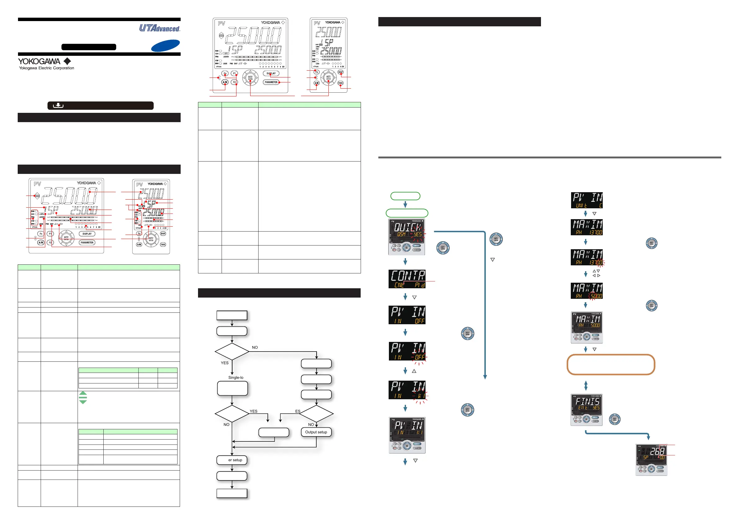
■ Making Settings Using Quick Setting Function
Example: SettingtoPIDcontrol,thermocoupletypeK (rangeof0.0to
500.0
0
C), and current control output
Forthedetailedprocedureandswitchingofdisplays,see"FlowofQuickSetting
Function"below.Fortheparameterstoset,seethenextpage.
(1)PresstheSET/ENTERkeywhileYESforQSM(Quicksettingmode)isdisplayed.
(2)Setthecontroltypeparameter(CNT)toPID(PIDcontrol).
(3)SetthePVinputtypeparameter(IN)toK1(-270.0to1370.0
0
C).
(4)SetthePVinputunitparameter(UNIT)toC(DegreeCelsius).
(5)SetthemaximumvalueofPVinputrangeparameter(RH)to500.0.
(6)SettheminimumvalueofPVinputrangeparameter(RL)to0.0.
(7)Settheoutputtypeselectionparameter(OT)toOUTterminals(current).
(8)Finally,EXITisdisplayed.ChangeNOtoYESandpresstheSET/ENTERkeyto
completethesetup.OperationDisplayappears.
Press the SET/ENTER key while YES
is displayed to start the Quick setting.
[NO]
arrow key and press the
SET/ENTER key.
Select NO to return to
the Operation Display.
Power-on
First, the control type
parameter (CNT)
is displayed.
Initial value: PID (PID control)
Press the Down arrow key.
The PV input type
parameter (IN) is
displayed.
Initial value: OFF
Press the SET/ENTER key.
OFF blinks.
Blinking allows you to
change the setting.
Press the Up arrow key.
K1 is displayed.
K1 has been registered.
Press the SET/ENTER key.
Press the Down arrow key.
[YES]
Quick setting starts
The last digit of the upper limit value blinks.
The parameter RH (maximum value of PV input range)
has been changed to 500.0.
The setpoint for the parameter RH has been registered.
Press the Down arrow key.
Operation Display
.
.
.
1.
2.
The PV input unit parameter (UNIT) is displayed.
Initial value: C (Degree Celsius)
Press the Down arrow key.
Follow the same procedure to set RL
to 0.0 and OT to 00.02.
Set other parameters as needed.
input value (PV).
Displays the target
setpoint (SP).
Finally, EXIT is displayed.
Press the SET/ENTER key to swtich to the setting mode.
Change NO to YES and press the SET/ENTER key
to complete the setup of the basic function.
Operation Display appears.
The Quick setting function continues in the NO state.
The upper limit value of the setting range is displayed
for the parameter RH (maximum value of PV input range).
Press the SET/ENTER key.
Press the SET/ENTER key.
Change the setpoint using the Up/Down arrow keys
to increase and decrease the value and the Left/Right arrow
keys to move between digits.
■ FlowofQuickSettingFunction
InQuicksettingmode,theparameterguideappearsonPVdisplay.
Thisguidecanbeturnedon/offwiththeFnkey.

 Loading...


