IM 05P01C31-15EN page 9/12
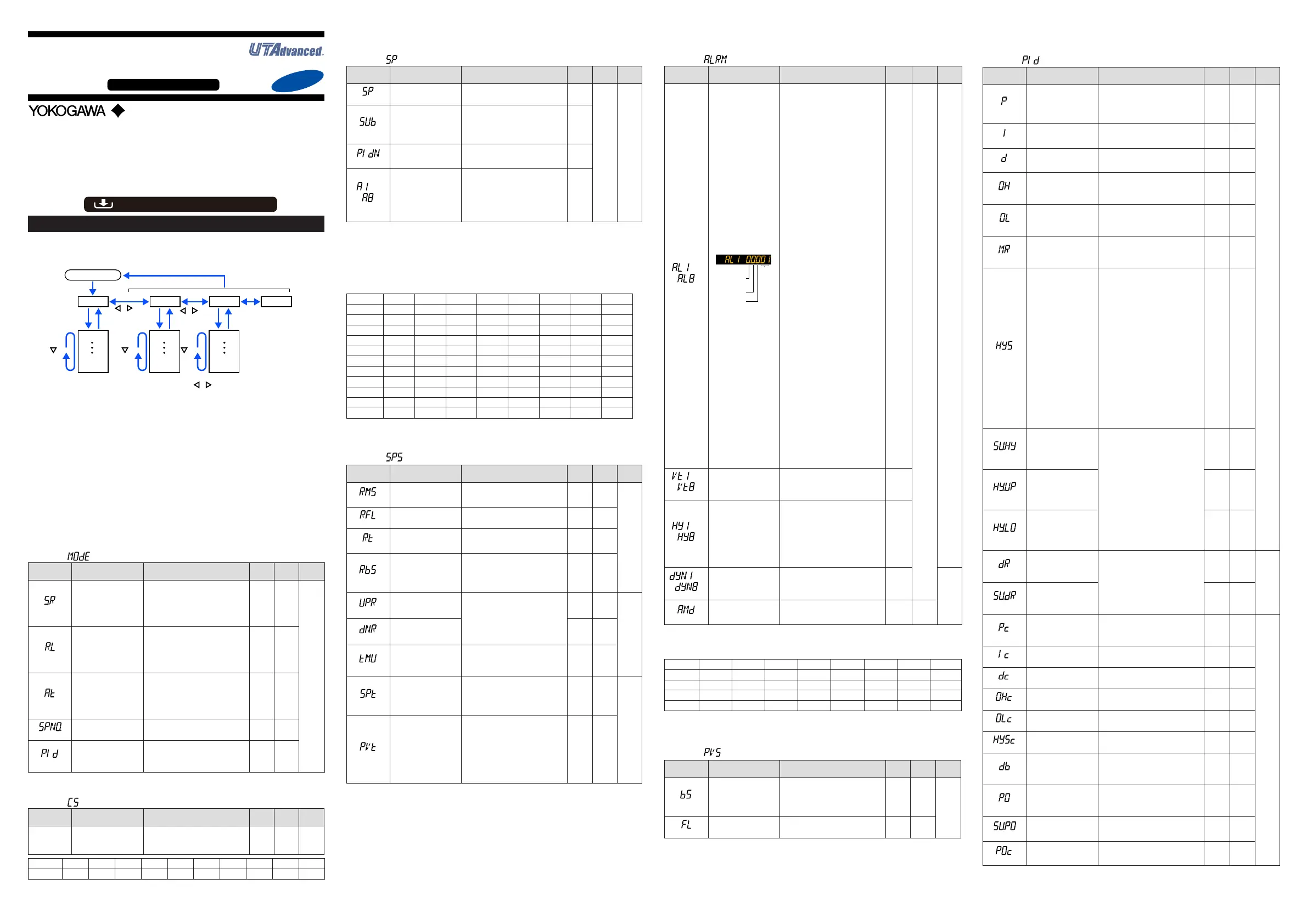
Operation Parameters
HolddownthePARAMETERkeyorPARAkeyfor3secondstomovefromtheOpera-
tionDisplaytotheOperationParameterSetting Display.PresstheDISPLAYkeyor
DISPkeyoncetoreturntotheOperationDisplay.
Menu
Hold down PARAMETER key or PARA key
for 3 sec.
DISPLAY key
or DISP key
PARAMETER key
or PARA key
key key key
key
key
The parameter groups can be switched using , keys.
Operation Dsipaly
Parameter
Parameter
Parameter
Parameter
Parameter
Parameter
END
Menu
END
Menu END
END
Menu Display and
Parameter Setting
Display are changed
in a circular pattern.
Move to the Setup Parameter Setting Display:
Hold down the PARAMETER key or PARA key and the Left arrow key simultaneously
for 3 sec.
Operation for Setting
· Toselecttheparametersettingdisplayedastheinitialvalue,presstheDownarrow
keytomovetothenextparameter.
· Tochangeandsettheparametersetting,presstheSET/ENTERkeytostarttheset-
pointblinking.Theblinkingstateallowsyoutomakechanges(settingmode).Usethe
Up/Down/Left/Rightarrowkeystochangethesetpoint.PresstheSET/ENTERkeyto
registerthesetting.
Notethattherearesomeparameterswhicharenotdisplayeddependingonthemodelandsufx
codes,controlmode(CTLM),controltype (CNT),etc.Theparametersforprofessional setting
mode(LEVL:PRO)arenotdescribedinthismanual.SeeUser’sManual(IM05P01C31-01EN).
■ Operation Mode
Menusymbol:
(MODE)
Parameter
symbol
Name of Parameter Setting Range
Initial
value
User
setting
Display
level
(S.R)
STOP/RUNswitch
STOP:Stopmode
RUN:Runmode
Presetoutput(PO)isgeneratedin
STOPmode.
Default:Notdisplayed.STOP/RUN
switchisassignedtocontactinput.
RUN
EASY
(R.L)
REMOTE/LOCALswitch
LCL:Localmode
REM:Remotemode
Select a remote input method for
acquiringthetargetsetpointfrom
remoteinputorcommunicationusing
theparameterRMS.
LCL
(AT)
AUTO-tuningswitch
OFF:Disable
1to8:Performauto-tuning.Tuning
resultisstoredinthespeciednum-
beredPID.
R:TuningresultisstoredinthePID
forreferencedeviation.
OFF
(SPNO.)
SPnumberselection
1to8(Dependsonthesetupparam-
eterSPGR.setting.)
1
(PID)
PIDnumber
ThePIDgroupnumberbeingselected
is displayed.
1to8,R:PIDgroupforreference
deviation
1
■ SELECT Parameter
Menusymbol: (CS)
Parameter
symbol
Name of Parameter Setting Range
Initial
value
User
setting
Display
level
Registered
parameter
symbol
SELECTparameter10
to19
Settingrangeofaregisteredparame-
ter.Fordetails,seeUser'sManual(IM
05P01C31-01EN).
—
Table
below
EASY
Parameter n=10 n=11 n=12 n=13 n=14 n=15 n=16 n=17 n=18 n=19
CSn
FortheregistrationofSELECTparameters,seeUser'sManual(IM05P01C31-01EN).
■ SP and Alarm Setpoint Setting Parameter
Menusymbol: (SP)
Parameter
symbol
Name of Parameter Setting Range
Initial
value
User
setting
Display
level
(SP)
Targetsetpoint
0.0to100.0%ofPVinputrange(EU)
(Settingrange:SPLtoSPH)
SPL
Table
below
EASY
(SUB)
Sub-targetsetpoint(in
Two-positiontwo-level
control)
Set the offset from SP.
-100.0to100.0%ofPVinputrange
span(EUS)
0.0%
ofPV
input
range
span
(PIDN)
PIDnumberselection
SetaPIDgroupnumbertouse.
1to8(Dependsonthesetupparam-
eterPIDG.setting.)
1to8
to
(A1toA8)
Alarm-1to-8setpoint
SetadisplayvalueofsetpointofPV
alarm,SPalarm,deviationalarm,
outputalarm,orvelocityalarm.
-19999to30000(Setavaluewithinthe
inputrange.)
Decimalpointpositiondependsonthe
input type
0
FortheparameterSP(targetsetpoint),8groupsaredisplayedforthefactorydefault.
ThenumberofgroupscanbechangedbythesetupparameterSPGR.(numberofSP
groups).Forthealarm setpointparameter,alarm-1 to-4aredisplayed forthefactory
default.Thenumberofalarms canbechangedusingthe setupparameterALNO.
(numberofalarms).TochangethenumberofSPgroupsoralarms,seeUser'sManual
(IM05P01C31-01EN).
UsethefollowingtabletorecordSPandalarmsetpoints.
Parameter n=1 n=2 n=3 n=4 n=5 n=6 n=7 n=8
SP
SUB
PIDN
A1
A2
A3
A4
A5
A6
A7
A8
n:groupnumber
■ SP-related Setting Parameter
Menusymbol: (SPS)
Parameter
symbol
Name of Parameter Setting Range
Initial
value
User
setting
Display
level
(RMS)
Remoteinputmethod
RSP:Viaremote(auxiliaryanalog)
input
COM:Viacommunication.
RSP
STD
(RFL)
Remoteinputlter OFF,1to120s OFF
(RT)
Remoteinputratio
SP=RemoteinputxRT+Remote
inputbias
0.001to9.999
1.000
(RBS)
Remoteinputbias
-100.0to100.0%ofPVinputrange
span(EUS)
0.0%
ofPV
input
range
span
(UPR)
SPramp-uprate
UsedtopreventSPfromchanging
suddenly.
Setaramp-uprateorramp-downrate
per hour or minute. Set a time unit
usingtheparameterTMU.
OFF,0.0+1digitto100.0%ofPV
inputrangespan(EUS)
OFF
EASY
(DNR)
SPramp-downrate OFF
(TMU)
SPramp-ratetimeunit
HOUR:Ramp-uprateorramp-down
rate per hour
MIN:Ramp-uprateorramp-down
rate per minute
HOUR
(SPT)
SPtrackingselection
Trackingisperformedwhenthemode
changesfromRemotetoLocal.(The
local setpoint keeps track of the
remotesetpoint.)
OFF,ON
ON
STD
(PVT)
PVtrackingselection
Causesthesetpointtokeeptrackof
thePVsothesetpointautomatically
revertstoitsoriginalvalueatapreset
rateofchange.TheUPR,DNR,and
TMUareusedincombination.Operat-
ingconditions:1)MAN→AUTO,2)
STOP→AUTO,3)Power-on,4)SP
numberchange,5)SPchange
OFF,ON
OFF
■ Alarm Function Setting Parameter
Menusymbol: (ALRM)
Parameter
symbol
Name of Parameter Setting Range
Initial
value
User
setting
Display
level
to
(AL1toAL8)
Alarm-1to8type
Example:Alarm-1
Stand-by
action
Latch action
Energized/
De-energize
Alarm
type
Seta5-digitvalueinthefollowing
order.
[Latchaction(0/1/2/3/4)]+[Energized
(0)orDe-energized(1)]+[Without(0)
orWith(1)Stand-byaction]+[Alarm
type:2digits(seebelow)]
Forlatchaction,seeUser'sManual
(IM05P01C31-01EN).
AL1,
AL3,
AL5,
AL7:
Latch
action
(0)
Ener-
gized
(0)
Without
Stand-
by
action
(0)
PV
high
limit(01)
AL2,
AL4,
AL6,
AL8:
Latch
action
(0)
Ener-
gized
(0)
Without
Stand-
by
action
(0)
PVlow
limit(02)
AL5to
AL8:not
displayed
for
factory
default
Table
below
EASY
Alarmtype:2digits
00:Disable
01:PVhighlimit
02:PVlowlimit
03:SPhighlimit
04:SPlowlimit
05:Deviationhighlimit
06:Deviationlowlimit
07:Deviationhighandlowlimits
08:
Deviationwithinhighandlowlimits
09:TargetSPhighlimit
10:TargetSPlowlimit
11:TargetSPdeviationhighlimit
12:TargetSPdeviationlowlimit
13:
TargetSPdeviationhighandlowlimits
14:TargetSPdeviationwithinhigh
and low limits
15:OUThighlimit
16:OUTlowlimit
17:Cooling-sideOUThighlimit
18:Cooling-sideOUTlowlimit
19:AnaloginputPVhighlimit
20:AnaloginputPVlowlimit
21:AnaloginputRSPhighlimit
22:AnaloginputRSPlowlimit
23:AnaloginputAIN2highlimit
24:AnaloginputAIN2lowlimit
25:AnaloginputAIN4highlimit
26:AnaloginputAIN4lowlimit
27:Feedbackinputhighlimit
28:Feedbackinputlowlimit
29:PVvelocity
30:Faultdiagnosis
31:FAIL
32:Deviation(%)highlimit
33:Deviation(%)lowlimit
34:Deviation(%)highandlowlimits
35:Deviation(%)withinhighandlow
limits
36:TargetSPdeviation(%)highlimit
37:TargetSPdeviation(%)lowlimit
38:TargetSPdeviation(%)highand
low limits
39:TargetSPdeviation(%)withinhigh
and low limits
to
(VT1toVT8)
PVvelocityalarmtime
setpoint1to8
0.01to99.59(minute.second) 1.00
to
(HY1toHY8)
Alarm-1to-8hysteresis
Setadisplayvalueofsetpointof
hysteresis.
-19999to30000(Setavaluewithin
theinputrange.)
Decimalpointpositiondependsonthe
inputtype.Whenthedecimalpoint
positionfortheinputtypeissetto"1",
theinitialvalueofthehysteresisis
"1.0".
10
to
(DYN1toDYN8)
Alarm-1to-8On-delay
timer
AnalarmoutputisONwhenthedelay
timerexpiresafterthealarmsetpoint
is reached.
0.00to99.59(minute.second)
0.00
STD
(AMD)
Alarmmode
0:Alwaysactive
1:NotactiveinSTOPmode
2:NotactiveinSTOPorMANmode
0
Forthealarmfunctionsettingparameter,4alarmsaredisplayedforthefactorydefault.
Thenumberofalarmscan bechangedbythesetup parameterALNO.(numberof
alarms).Tochangethenumberofalarms,seeUser'sManual(IM05P01C31-01EN).
Parameter n=1 n=2 n=3 n=4 n=5 n=6 n=7 n=8
ALn
VTn
HYn
DYNn
n:alarmnumber
■ PV-related Setting Parameter
Menusymbol: (PVS)
Parameter
symbol
Name of Parameter Setting Range
Initial
value
User
setting
Display
level
(BS)
PVinputbias
-100.0to100.0%ofPVinputrange
span(EUS)
0.0%
ofPV
input
range
span
EASY
(FL)
PVinputlter OFF,1to120s OFF
■ PID Setting Parameter
Menusymbol: (PID)
Parameter
symbol
Name of Parameter Setting Range
Initial
value
User
setting
Display
level
(P)
Proportionalband
Heating-sideproportion-
alband(inHeating/cool-
ingcontrol)
0.0to999.9%
When0.0%isset,itoperatesas
0.1%.
Heating-sideON/OFFcontrolapplies
when0.0%inHeating/coolingcontrol
5.0%
EASY
(I)
Integraltime
Heating-sideintegraltime
(inHeating/coolingcontrol)
OFF:Disable
1to6000s
240s
(D)
Derivativetime
Heating-sidederivativetime
(inHeating/coolingcontrol)
OFF:Disable
1to6000s
60s
(OH)
Controloutputhighlimit
Heating-sidecontrol
outputhighlimit(in
Heating/coolingcontrol)
-4.9to105.0%,(OL<OH)
InHeating/coolingcontrol:0.1to
105.0%(OL<OH)
100.0%
(OL)
Controloutputlowlimit
Heating-sidecontrol
outputlowlimit(inHeat-
ing/coolingcontrol)
-5.0to104.9%,(OL<OH),SD:Tight
shut
InHeating/coolingcontrol:0.0to
104.9%(OL<OH)
0.0%
(MR)
Manual reset
EnabledwhenintegraltimeisOFF.
Themanualresetvalueequalsthe
outputvaluewhenPV=SP.
-5.0to105.0%
50.0%
(HYS)
Hysteresis(inON/OFF
control,Position
proportionalcontrol,or
Two-positiontwo-level
control)
Heating-sideON/OFF
controlhysteresis(in
Heating/coolingcontrol)
InON/OFFcontrolorTwo-position
two-levelcontrol:0.0to100.0%of
PVinputrangespan(EUS)
InHeating/coolingcontrolorPosition
proportionalcontrol:0.0to100.0%
In
ON/OFF
control
or
Two-
position
two-level
control:
0.5%of
PVinput
range
span
In Heat
-
ing/
cooling
control
or
Position
proportional
control:
0.5%
(SU.HY)
Sub-hysteresis(in
Two-positiontwo-level
control)
0.0to100.0%ofPVinputrange
span(EUS)
0.5%
ofPV
input
range
span
(HY.UP)
Upper-sidehysteresis
(inON/OFFcontrol)
0.5%
ofPV
input
range
span
(HY.LO)
Lower-sidehysteresis
(inON/OFFcontrol)
0.5%
ofPV
input
range
span
(DR)
Direct/reverseaction
switch
RVS:Reverseaction
DIR:Directaction
RVS
STD
(SU.DR)
Sub-direct/reverse
actionswitch(inTwo-
positiontwo-level
control)
DIR
(Pc)
Cooling-sidepropor-
tionalband
0.0to999.9%
(Cooling-sideON/OFFcontrolap-
plieswhen0.0%inHeating/cooling
control)
5.0%
EASY
(Ic)
Cooling-sideintegral
time
OFF:Disable
1to6000s
240s
(Dc)
Cooling-sidederivative
time
OFF:Disable
1to6000s
60s
(OHc)
Cooling-sidecontrol
outputhighlimit
0.1to105.0%,(OLc<OHc) 100.0%
(OLc)
Cooling-sidecontrol
output low limit
0.0to104.9%,(OLc<OHc) 0.0%
(HYSc)
Cooling-sideON/OFF
control hysteresis
0.0to100.0% 0.5%
(DB)
Outputdeadband(in
Heating/coolingcontrol
or Position proportional
control)
InHeating/coolingcontrol:-100.0to
50.0%
InPositionproportionalcontrol:1.0
to10.0%
3.0%
(PO)
Preset output
Heating-sidepreset
output(inHeating/cool-
ingcontrol)
InSTOPmode,xedcontroloutput
canbegenerated.InPositionpropor-
tionalcontrol,Valveopeningcanbe
set;-5.0to105.0%
0.0%
(SU.PO)
Sub-presetoutput(in
Two-positiontwo-level
control)
InSTOPmode,xedsub-control
outputcanbegenerated.
0%,100%
0%
(POc)
Cooling-sidepreset
output
InSTOPmode,cooling-sidexed
controloutputcanbegenerated.
-5.0to105.0%
0.0%
ForthePIDsettingparameter,8groupsaredisplayedforthefactorydefault.
Thenumberofgroups canbechangedbythe setupparameterPIDG.(number ofPID
groups).TochangethenumberofPIDgroups,seeUser'sManual(IM05P01C31-01EN).
Operation
Guide
UT55A, UT52A
Digital Indicating Controller
(Panel Mounting Type)
Operation Guide for Single-loop Control
Yokogawa Electric Corporation
Parameters
For details of the each function, refer to the electronic manual. Manuals can be
downloaded or viewed at the following URL.
Functional
Enhancement
http://www.yokogawa.com/ns/ut/im/
This operation guide describes the functions of parameters briefly. The parameter
symbols listed are in the order shown on the display in each group of menu symbols.
In addition, each parameter table has a “User Setting” column, where you can record
your setpoints when setting them in the controller. The scrolling guide is displayed on PV
display in the Parameter Setting Display. This guide can be turned on/off with the Fn key.
«Detailed Code Model»

 Loading...


