IM 05P01C31-15EN page 6/12
■ Parameterstobeset
Control Type
Parameter Symbol Name of Parameter Setting Range
CNT Controltype
PID:PIDcontrol
ONOF:ON/OFFcontrol(1pointofhysteresis)
ONOF2:ON/OFFcontrol(2pointsofhysteresis)
2P2L:Two-positiontwo-levelcontrol
H/C:Heating/coolingcontrol
S-PI:SamplePIcontrol
BATCH:BatchPIDcontrol
FFPID:Feedforwardcontrol
Note: Somesetpointsmaynotbedisplayeddependingonthemodelandsuffixcodes.
Input Function
Parameter Symbol Name of Parameter Setting Range
IN PVinputtype
OFF:Disable
K1:-270.0to1370.0
0
C/-450.0to2500.0
0
F
K2:-270.0to1000.0
0
C/-450.0to2300.0
0
F
K3:-200.0to500.0
0
C/-200.0to1000.0
0
F
J:-200.0to1200.0
0
C/-300.0to2300.0
0
F
T1:-270.0to400.0
0
C/-450.0to750.0
0
F
T2:0.0to400.0
0
C/-200.0to750.0
0
F
B:0.0to1800.0
0
C/32to3300
0
F
S:0.0to1700.0
0
C/32to3100
0
F
R:0.0to1700.0
0
C/32to3100
0
F
N:-200.0to1300.0
0
C/-300.0to2400.0
0
F
E:-270.0to1000.0
0
C/-450.0to1800.0
0
F
L:-200.0to900.0
0
C/-300.0to1600.0
0
F
U1:-200.0to400.0
0
C/-300.0to750.0
0
F
U2:0.0to400.0
0
C/-200.0to1000.0
0
F
W:0.0to2300.0
0
C/32to4200
0
F
PL2:0.0to1390.0
0
C/32.0to2500.0
0
F
P2040:0.0to1900.0
0
C/32to3400
0
F
WRE:0.0to2000.0
0
C/32to3600
0
F
JPT1:-200.0to500.0
0
C/-300.0to1000.0
0
F
JPT2:-150.00to150.00
0
C/-200.0to300.0
0
F
PT1:-200.0to850.0
0
C/-300.0to1560.0
0
F
PT2:-200.0to500.0
0
C/-300.0to1000.0
0
F
PT3:-150.00to150.00
0
C/-200.0to300.0
0
F
0.4-2V:0.400to2.000V
1-5V:1.000to5.000V
4-20:4.00to20.00mA
0-2V:0.000to2.000V
0-10V:0.00to10.00V
0-20:0.00to20.00mA
-1020:-10.00to20.00mV
0-100:0.0to100.0mV
UNIT PVinputunit
-:Nounit,C:DegreeCelsius
-:Nounit,--:Nounit,---:Nounit,F:DegreeFahrenheit
RH
Maximumvalueof
PVinputrange
Dependsontheinputtype.
-Fortemperatureinput-
Setthetemperaturerangethatisactuallycontrolled.
(RL<RH)
-Forvoltage/currentinput-
Settherangeofavoltage/currentsignalthatisapplied.
Thescaleacrosswhichthevoltage/currentsignalis
actuallycontrolledshouldbesetusingthemaximumvalue
ofinputscale(SH)andminimumvalueofinputscale(SL).
(Inputisalways0%whenRL=RH.)
RL
Minimumvalueof
PVinputrange
SDP
PVinputscale
decimal point
position
0:Nodecimalplace
1:Onedecimalplace
2:Twodecimalplaces
3:Threedecimalplaces
4:Fourdecimalplaces
SH
Maximumvalueof
PVinputscale
-19999to30000,(SL<SH),|SH-SL|≤30000
SL
Minimumvalueof
PVinputscale
Note1:SDP,SH,andSLaredisplayedonlyforvoltage/currentinput.
Note2:W:W-5%Re/W-26%Re(HoskinsMfg.Co.),ASTME988
Output Function
Parameter Symbol Name of Parameter Setting Range
OT
Outputtypeselection
Upper two digits
Lower two digits
ControloutputorHeating-
sidecontroloutput(Lower
twodigits)
00:OFF
01:OUTterminals
(voltagepulse)
02:OUTterminals(current)
03:
OUTterminals(relay/triac)
04:OUT2terminals
(voltagepulse)
05:OUT2terminals(current)
06:
OUT2terminals(relay/triac)
Cooling-sidecontroloutput
(Uppertwodigits)
00:OFF
01:OUTterminals
(voltagepulse)
02:OUTterminals(current)
03:
OUTterminals(relay/triac)
04:OUT2terminals
(voltagepulse)
05:OUT2terminals(current)
06:
OUT2terminals(relay/triac)
CT
Controloutputcycle
time
Heating-sidecontrol
output cycle time
(inHeating/cooling
control)
0.5to1000.0s
CTc
Cooling-sidecontrol
output cycle time
4.
Adjusting Valve Position Automatically
(for a Position Proportional Type Controller Only)
Thefollowingoperatingproceduredescribeshowtoinputfeedbacksignalsfromthe
controlvalveandadjustthefully-openandfully-closedpositionsofthecontrolvalve
automatically.Thefully-openandfully-closedpositionsofthevalvecanbeadjusted
automaticallybyinputtingfeedbacksignalsfromthevalve.Toadjustthevalveposi-
tion,youneedtocarryouttheconnectionandbringthecontrollerintomanualmode.
Fortheconnection,see“6. TerminalWiringDiagrams”in"Installationand Wiring",
andforthemanualmode, see“5.SwitchingbetweenAUTO andMAN”in"Opera-
tions."
CTL menu is displayed.
Press the Right arrow key until OUT menu appears.
Press the SET/ENTER key.
Press the SET/ENTER key.
Press the Up arrow key.
Hold down the keys for 3 seconds.
+
Show the Operation Display.
OUT menu is displayed.
OFF blinks.
Press the SET/ENTER key.
2.
3.
4.
5.
6.
7.
* When a password is set, PASS is displayed.
If the correct password is not entered, setup
parameters cannot be changed.
The parameter V.AT (automatic valve
position adjustment) is displayed.
ON is displayed.
Blinks during the change.
● When the adjustment is completed normally, the indication
automatically returns to OFF.
● When VAT.E appears on PV display, it indicates an error.
Check the wiring for feedback input and perform the
automatic adjustment again. To perform a valve adjustment
manually, see User’s Manual (IM 05P01C31-01EN).
ON has been registered and the automatic
adjustment of the valve position starts.
V.AT blinks during the automatic adjustment.
After the adjustment is completed, press
the DISPLAY key or DISP key once to return
to the Operation Display.
5. Setting Alarm Type
Thefollowingoperatingprocedureshowsanexampleofchangingthealarm-1type
(factorydefault:PVhighlimitalarm)toPVlowlimitalarm(setpoint:02).
MODE menu is displayed.
Press the Right arrow key until ALRM menu appears.
Press the SET/ENTER key.
Press the SET/ENTER key.
Hold down the key for 3 seconds.
Show the Operation Display.
ALRM menu is displayed.
The parameter AL1 (alarm-1 type) is
displayed.
Press the SET/ENTER key.
Energized/De-energized
Latch action
Stand-by action
The alarm-1 type setpoint 02 (PV low limit)
is registered.
After the setup is completed, press the DISPLAY key
or DISP key once to return to the Operation Display.
Symbol
● To change the alarm type, change the last 2 digits of the
5-digit value.
● Stand-by action and excitation are turned on or off by
selecting 1 or 0. (See “ Setting Display of Alarm Type.”)
●
For the latch action, see User ’s Manual (IM 05P01C31-01EN).
The last digit of the setpoint blinks.
Change the setpoint using the Up/Down arrow keys
to increase and decrease the value and
the Left/Right arrow keys to move between digits.
Hysteresis
Alarm setpoint
PV, RSP, AIN2
or AIN4
SP or Target SP
Hysteresis
PV
Deviation setpoint
SP or Target SP
Deviation
setpoint
PV
Hysteresis
Hysteresis
Open
(unlit)
Closed
(lit)
SP or Target SP
PV
Deviation setpoint
Hysteresis
- -
SP or Target SP
PV
Hysteresis
Hysteresis
Deviation
setpoint
Open
(unlit)
SP or
Target SP
Alarm setpoint
Hysteresis
SP or
Target SP
Hysteresis
Alarm setpoint
Alarm setpoint
Output
Hysteresis
Closed
(lit)
Hysteresis
Alarm setpoint
Output
Alarm setpoint
Hysteresis
PV, RSP, AIN2
or AIN4
Hysteresis
Alarm setpoint
PV, RSP, AIN2
or AIN4
SP or Target SP
Hysteresis
PV
Deviation setpoint
SP or Target SP
Deviation
setpoint
PV
Hysteresis
Hysteresis
SP or Target SP
PV
Deviation setpoint
Hysteresis
SP or Target SP
PV
Hysteresis
Hysteresis
Deviation
setpoint
Closed
(unlit)
SP or
Target SP
Alarm setpoint
Hysteresis
SP or
Target SP
Hysteresis
Alarm setpoint
Alarm setpoint
Hysteresis
PV, RSP, AIN2
or AIN4
Alarm setpoint
Output
Hysteresis
Hysteresis
Alarm setpoint
Output
Setting Display of Alarm Type Stand-by Action
Energized (0) / De-energized (1)
Alarm type
Without (0) or With (1)
Stand-by action
Latch action (0/1/2/3/4)
See
User’s Manual (IM 05P01C31-01EN).
PV low limit
alarm setpoint
Treated
as normal
ºC
Power-on
Time
The alarm output does not turn on
in this region even if the PV valule
is below PV low limit alarm setpoint.
Normal Abnormal
The alarm output
turns on.
No alarm (00)
Alarm Action (De-energized)
PV high limit (01)
Analog input PV high limit (19)
Analog input RSP high limit (21)
Analog input AIN2 high limit (23)
Analog input AIN4 high limit (25)
PV low limit (02)
Analog input PV low limit (20)
Analog input RSP low limit (22)
Analog input AIN2 low limit (24)
Analog input AIN4 low limit (26)
SP high limit (03)
Target SP high limit (09)
SP low limit (04)
Target SP low limit (10)
Deviation high limit (05)
Target SP deviation high
limit (11)
Deviation low limit (06)
Target SP deviation low limit (12)
Deviation high and low
limits (07)
Target SP deviation high and
low limits (13)
Deviation within high and low
limits (08)
Target SP deviation within high
and low limits (14)
Control output high limit (15)
Cooling-side control output
high limit (17)
Control output low limit (16)
Cooling-side control output
low limit (18)
Feedback input high limit (27)
Feedback input low limit (28)
PV velocity (29)
Fault diagnosis alarm (30)
FAIL (31)
Alarm Type (Alarm Setpoint) Alarm Action (Energized)
Open
(unlit)
Open
(unlit)
Open
(lit)
Closed
(lit)
Open
(unlit)
Open
(lit)
Closed
(unlit)
Closed
(
unlit
)
Open
(lit)
Closed
(unlit)
Closed
(unlit)
Open
(lit)
Open
(lit)
Closed
(lit)
Closed
(lit)
Closed
(lit)
Closed
(lit)
Closed
(lit)
Closed
(lit)
Closed
(lit)
Closed
(lit)
Open
(unlit)
Open
(unlit)
Open
(unlit)
Open
(unlit)
Open
(unlit)
Open
(unlit)
Open
(lit)
Open
(lit)
Open
(lit)
Open
(lit)
Open
(lit)
Open
(lit)
Closed
(unlit)
Closed
(unlit)
Closed
(unlit)
Closed
(unlit)
Closed
(unlit)
Closed
(unlit)
Burnout of PV input, RSP remote input, or AIN2/AIN4 auxiliary
analog input. ADC failure, RJC error.
For the factory default, the contact output is turned ON in normal operation,
OFF at the time of FAIL. Control output: OFF or 0%, Alarm output: OFF
Note 1: “Open/closed” shows status of relay contact, and “lit/unlit” shows status of EV (event) lamp.
Note 2: Positive setpoint, Negative setpoint
Hysteresis
Alarm setpoint
PV, RSP, AIN2
or AIN4
SP or Target SP
Hysteresis
PV
Deviation setpoint
SP or Target SP
Deviation
setpoint
PV
Hysteresis
Hysteresis
Open
(unlit)
Closed
(lit)
SP or Target SP
PV
Deviation setpoint
Hysteresis
- -
SP or Target SP
PV
Hysteresis
Hysteresis
Deviation
setpoint
Open
(unlit)
SP or
Target SP
Alarm setpoint
Hysteresis
SP or
Target SP
Hysteresis
Alarm setpoint
Alarm setpoint
Output
Hysteresis
Closed
(lit)
Hysteresis
Alarm setpoint
Output
Alarm setpoint
Hysteresis
PV, RSP, AIN2
or AIN4
Hysteresis
Alarm setpoint
PV, RSP, AIN2
or AIN4
SP or Target SP
Hysteresis
PV
Deviation setpoint
SP or Target SP
Deviation
setpoint
PV
Hysteresis
Hysteresis
SP or Target SP
PV
Deviation setpoint
Hysteresis
SP or Target SP
PV
Hysteresis
Hysteresis
Deviation
setpoint
Closed
(unlit)
SP or
Target SP
Alarm setpoint
Hysteresis
SP or
Target SP
Hysteresis
Alarm setpoint
Alarm setpoint
Hysteresis
PV, RSP, AIN2
or AIN4
Alarm setpoint
Output
Hysteresis
Hysteresis
Alarm setpoint
Output
Setting Display of Alarm Type
Stand-by Action
Energized (0) / De-energized (1)
Alarm type
Without (0) or With (1)
Stand-by action
Latch action (0/1/2/3/4)
See
User’s Manual (IM 05P01C31-01EN).
PV low limit
alarm setpoint
Treated
as normal
ºC
Time
The alarm output does not turn on
in this region even if the PV valule
is below PV low limit alarm setpoint.
Normal Abnormal
The alarm output
turns on.
No alarm (00)
Alarm Action (De-energized)
PV high limit (01)
Analog input PV high limit (19)
Analog input RSP high limit (21)
Analog input AIN2 high limit (23)
Analog input AIN4 high limit (25)
PV low limit (02)
Analog input PV low limit (20)
Analog input RSP low limit (22)
Analog input AIN2 low limit (24)
Analog input AIN4 low limit (26)
SP high limit (03)
Target SP high limit (09)
SP low limit (04)
Target SP low limit (10)
Deviation high limit (05)
Target SP deviation high
limit (11)
Deviation low limit (06)
Target SP deviation low limit (12)
Deviation high and low
limits (07)
Target SP deviation high and
low limits (13)
Deviation within high and low
limits (08)
Target SP deviation within high
and low limits (14)
Control output high limit (15)
Cooling-side control output
high limit (17)
Control output low limit (16)
Cooling-side control output
low limit (18)
Feedback input high limit (27)
Feedback input low limit (28)
PV velocity (29)
Fault diagnosis alarm (30)
FAIL (31)
Alarm Type (Alarm Setpoint) Alarm Action (Energized)
Open
(unlit)
Open
(unlit)
Open
(lit)
Closed
(lit)
Open
(unlit)
Open
(lit)
Closed
(unlit)
Closed
(
unlit
)
Open
(lit)
Closed
(unlit)
Closed
(unlit)
Open
(lit)
Open
(lit)
Closed
(lit)
Closed
(lit)
Closed
(lit)
Closed
(lit)
Closed
(lit)
Closed
(lit)
Closed
(lit)
Closed
(lit)
Open
(unlit)
Open
(unlit)
Open
(unlit)
Open
(unlit)
Open
(unlit)
Open
(unlit)
Open
(lit)
Open
(lit)
Open
(lit)
Open
(lit)
Open
(lit)
Open
(lit)
Closed
(unlit)
Closed
(unlit)
Closed
(unlit)
Closed
(unlit)
Closed
(unlit)
Closed
(unlit)
Burnout of PV input, RSP remote input, or AIN2/AIN4 auxiliary
analog input. ADC failure, RJC error.
For the factory default, the contact output is turned ON in normal operation,
OFF at the time of FAIL. Control output: OFF or 0%, Alarm output: OFF
Note 1: “Open/closed” shows status of relay contact, and “lit/unlit” shows status of EV (event) lamp.
Note 2: Positive setpoint, Negative setpoint
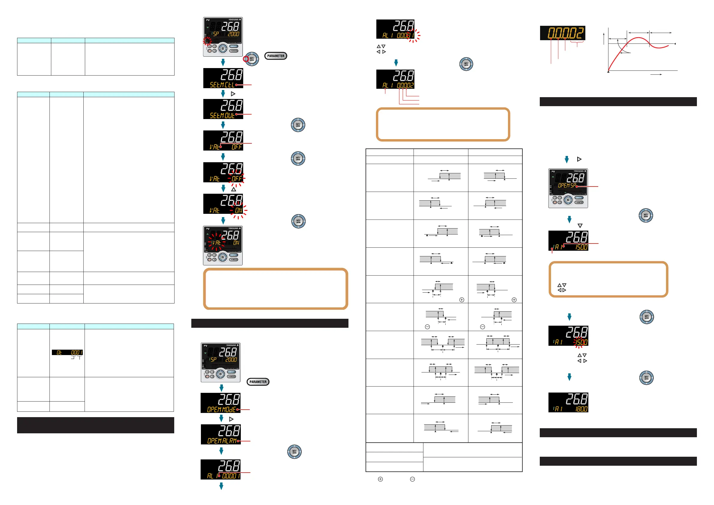
6. Setting Alarm Setpoint
Thefollowingoperatingprocedureshowsanexampleofsettingthealarm-1setpoint
ofgroup1to180.0.
Beforesettingthealarmsetpoint,checkthealarmtype.
Tochangethealarmtype,see“5.SettingAlarmType.”
Press the Right arrow key.
Press the SET/ENTER key.
SP menu is displayed.
Display the parameter and group
that need to be changed.
Blinks during the change.
The setpoint has been registered.
After the setup is completed, press
the DISPLAY key or DISP key once
to return to the Operation Display.
Press the SET/ENTER key.
Press the Down arrow key until A1 appears.
Press the SET/ENTER key.
Show the Operation Display.
Display MODE menu with the same procedure as described in
Setting Alarm Type.
Group
The parameter A1 is displayed.
A1 to A8 represent the alarm-1 to -8 setpoints.
Each parameter and group can be changed
in the Parameter Setting Displays of alarms
using arrow keys.
Up/Down arrow keys: parameters
Left/Right arrow keys: groups
Change the setpoint using the Up/Down arrow
keys to increase and decrease the value and
the Left/Right arrow keys to move between digits.
Initializing parameter values
Parametersthatyouhavechangedcanbeinitializedtofactorydefaultvaluesoruserdefault
values.Fordetails,see“ParameterInitialization”intheUser’sManual(IM05P01C31-01EN).
Changing the parameter display levels
Thisoperationguidedoesnot explainalltheparameters.To displayalltheparame-
ters,
youneedtochangetheparameterdisplayleveltoprofessionalsettingmode.For
details,see“SettingSecurityFunctions”intheUser’sManual(IM05P01C31-01EN).

 Loading...


