IM 05P01C31-15EN page 7/12
Contents
1. Monitoring-purposeOperationDisplaysAvailableduringOperation
2. SettingTargetSetpoint(SP)
3. Performing/CancelingAuto-tuning
4. SelectingTargetSetpointNumbers(SPNO.)
5. SwitchingbetweenAUTOandMAN
6. SwitchingbetweenRUNandSTOP
7. SwitchingbetweenREM(Remote)andLCL(Local)
8. ManipulatingControlOutputinManualMode
9. Troubleshooting
1. Monitoring-purpose Operation Displays Available during Operation
■
Operation Display Switching Diagram for Standard and Posi-
tion Proportional Types
• SP Display
DisplaysthemeasuredinputvalueonPVdisplay.
Displaysthetargetsetpoint(SP)onSetpointdisplay(SPcanbechanged).
• OUT Display
DisplaysthemeasuredinputvalueonPVdisplay.
Displaysthecontroloutputvalue(OUT)onSetpointdisplay(OUTcanbechanged
inmanualmode).
Displaysthevalve’sfeedbackinputvalue(at0to100%valveopening)inPosition
proportional control.
SP Display
OUT Display
(OUT can be changed.)
■
Operation Display Switching Diagram for Heating/Cooling Type
• SP Display
DisplaysthemeasuredinputvalueonPVdisplay.
Displaysthetargetsetpoint(SP)onSetpointdisplay(SPcanbechanged).
• OUT Display
DisplaysthemeasuredinputvalueonPVdisplay.
Displaysthecontroloutputvalues(C.H.)ofheatingandcoolingsidesonSetpoint
display(C.H.canbechangedinmanualmode).
SP Display
Heating/cooling OUT Display
AftershowingtheOUTDisplay,presstheDISPLAYkeyorDISPkeytoshowthefol-
lowingdisplaysconditionally.Fordetails,seeUser’sManual(IM05P01C31-01EN).
Standard, Position Proportional, and Heating/Cooling Types
• SELECTDisplays1to5(whichappearwhenregistered)
• AnalogInputDisplay(displayonly)(factorydefault:non-display)
•
PositionProportionalComputationOutputDisplay(displayonly)(factorydefault:non-display)
• PIDNumberDisplay(displayonly)(factorydefault:non-display)
•
HeaterBreakAlarm-1CurrentDisplay(displayonly)(forheaterbreakalarmoptiononly)
•
HeaterBreakAlarm-2CurrentDisplay(displayonly)(forheaterbreakalarmoptiononly)
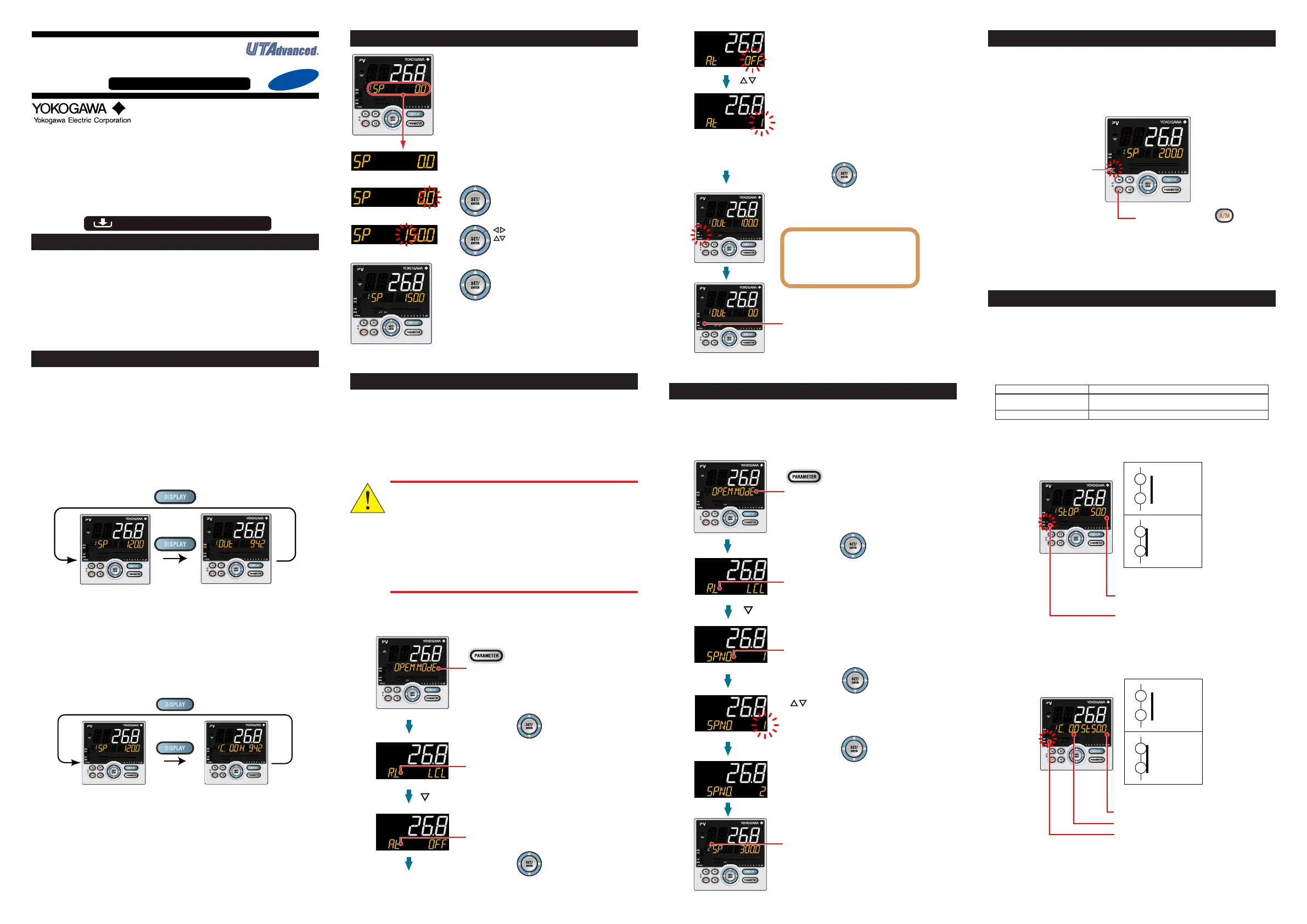
2. Setting Target Setpoint (SP)
When the required value is displayed,
press the SET/ENTER key to register
the setpoint.
Show the SP Display (Operation Display).
(This is an example of setting the target
setpoint to 150.0).
Press the SET/ENTER key to start the
last digit of the setpoint blinking.
Blinking allows you to change the value.
To set the setpoint, use the
Left/Right arrow keys to move
between digits and the Up/Down
arrow keys to increase and
decrease the value.
1.
2.
3.
4.
3. Performing/Canceling Auto-tuning
Auto-tuningshouldbeperformedaftersettingatargetsetpoint.
Makesurethatthecontrollerisinautomaticmode(AUTO)andinrunmode(RUN)
beforeauto-tuning.Forsetting toAUTO,see “5.SwitchingbetweenAUTO and
MAN,”andforsettingtoRUN,see“6.SwitchingbetweenRUNandSTOP.”
Ifthesetpointisknowninadvanceorauto-tuningdoesnotndanyappropriatePID
constants,setthePIDmanually.ForsettingthePIDmanually,seeUser’sManual(IM
05P01C31-01EN).
Do not perform auto-tuning for the following processes.
Tune PID manually.
• Processes with fast response such as flow rate control and pres-
sure control.
• Processes which do not allow the output to be turned on and off
even temporarily.
• Processes which prohibit severe output changes at control
valves (or other actuators).
• Processes in which product quality can be adversely affected if
PV values fluctuate beyond their allowable ranges.
Show the Operation Display.
Hold down the PARAMETER key or PARA key for
3 seconds to display MODE menu.
Press the SET/ENTER key.
Press the SET/ENTER key.
Press the Down arrow key until the parameter AT appears.
The parameter AT (auto-tuning switch) is displayed.
1.
2.
3.
4.
The parameter R.L (REMOTE/LOCAL switch)
is displayed.
Press the SET/ENTER key.
During auto-tuning,
• The MAN lamp blinks.
• The OUT symbol appears.
• The output values at 100.0% and
0% appear alternately.
OFF blinks.
Press the Up/Down arrow keys to display the required setpoint.
Blinks during the change.
The setpoint has been registered.
This starts auto-tuning.
The limiter can be set to the output during auto-tuning.
For details, see User’s Manual (IM 05P01C31-01EN).
The MAN lamp goes off, which means that
the auto-tuning completed normally.
The setting range is 1 to 8 (represent group numbers) or R.
To perform auto-tuning for the PID of group 1, set the parameter AT to 1.
To quit the auto-tuning, set the parameter to OFF.
4.
Selecting Target Setpoint Numbers (SPNO.)
Thefollowingoperatingprocedureshowsanexampleofchangingthetargetsetpoint
number(SPNO.)from1to2.EachSPhasitsPIDgroup.ThePIDgroupsetforthe
parameterPIDN(PIDnumberselection)isused.
Show the Operation Display.
Hold down the PARAMETER key or PARA key for
3 seconds to display MODE menu.
Press the SET/ENTER key.
SPNO. has been changed to 2.
Blinks during the change.
The setpoint has been registered.
Press the DISPLAY key or DISP key once
to return to the Operation Display.
Change the setpoint using
the Up/Down arrow keys.
Press the Down arrow key until the parameter SPNO.
appears.
Press the SET/ENTER key.
Press the SET/ENTER key.
The parameter R.L (REMOTE/LOCAL switch) is
displayed.
The parameter SPNO. (SP number selection)
is displayed.
UT55A, UT52A
Digital Indicating Controller
(Panel Mounting Type)
Operation Guide for Single-loop Control
This operation guide describes key entries for operating the UT55A and UT52A.
Although the display of UT55A is used in this guide, UT52A can be operated similarly.
For operations using external contact inputs, see “DI” of “6. Terminal Wiring Diagrams”
in “Installation and Wiring.”
If you cannot remember how to carry out an operation during setting, press the
DISPLAY key or DISP key once. This brings you to the display (Operation Display) that
appears at power-on.
The scrolling guide is displayed on PV display in the Parameter Setting Display.
This guide can be turned on/off with the Fn key.
Operations
For details of the each function, refer to the electronic manual. M
anuals can be
downloaded or viewed at the following URL.
Functional
Enhancement
http://www.yokogawa.com/ns/ut/im/
«Detailed Code Model»
5. Switching between AUTO and MAN
AUTOandMANswitchingcanbeperformedusinganyofthefollowing:(1)A/Mkey,
(2)Contactinput,(3)Communication,and(4)Userfunctionkey.
ThegurebelowshowsadirectoperationusingtheA/Mkey.
WhenAUTOandMAN switchingfunctionisassignedto thecontactinput,and the
contactinputisON,theswitchingbykeyoperationcannotbeperformed.
Fordetails,seeUser’sManual(IM05P01C31-01EN).
MAN lamp is lit in MAN mode.
Each time you press the key,
AUTO and MAN is switched alternately.
WhenAUTOisswitchedintoMAN,thecontroloutputvalueinAUTOmodeisheld.
Thecontrollercanbeoperatedmanuallyfromtheholdvalue.
Ifthemanualpreset outputisset(MPONparameter ≠OFF),thecontroller canbe
operatedmanuallyfromthearbitraryoutputvalue(MPO1toMPO5parameters).
6. Switching between RUN and STOP
RUNandSTOPswitchingcanbeperformedusinganyofthefollowing:(1)Contact
input,(2)Parameter,(3)Communication,and(4)Userfunctionkey.
Thefollowingshowsanexampleofswitchingusingthecontactinput.
(TheswitchingfunctionisassignedtoDI2contactforthefactorydefault.)
Fordetailsofotherswitchingmethodsandthedisplayappearingwhentheoperation
isstarted,seeUser’sManual(IM05P01C31-01EN).
Whenthecontrollerisstopped,inputandoutputsareasfollows:
PVinput DisplaysthePVvalue.
Controloutput Displaysthepresetoutputvalue.
ThepresetoutputvalueissetforeachPIDgroup.
Alarmoutput Turns the output on in case of an alarm.
Display in STOP mode
“STOP”isdisplayedonSymboldisplayand "presetoutputvalue"isdisplayedon
Datadisplay.
OFF: Operation RUN
Display in STOP mode
210
212
ON: Operation STOP
210
212
Preset output (PO)
Valve opening (0-100%) for
Position proportional type
STOP lamp is lit.
DI2
DI2
Display in STOP mode in Heating/cooling control
“Cooling-sidepresetoutputvalue” isdisplayedontheleft sideofthe“ST”symbol,
and“Heating-sidepresetoutputvalue”isontherightside.
OFF: Operation RUN
Display in STOP mode
210
212
ON: Operation STOP
210
212
Heating-side preset output (PO)
STOP lamp is lit
Cooling-side preset output (POc)
.
DI2
DI2

 Loading...


