IM 05P01C31-15EN page 3/12
Ratedmeasurementinputvoltage:Max.10VDC
Ratedtransientovervoltage:1500V(*)
*ThisisareferencesafetystandardvalueformeasurementcategoryIofCSA/UL61010-
1,andformeasurementcategoryOofIEC/EN61010-2-030.Thisvalueisnotnecessarilya
guaranteeofinstrumentperformance.
• EMCstandards:
CompliantwithCEmarking
EN61326-1ClassA,Table2(Foruseinindustriallocations),
EN61326-2-3
*Theinstrumentcontinuestooperateatameasurementaccuracyofwithin±20%ofthe
rangeduringtesting.
EN55011ClassA,Group1
EN61000-3-2ClassA
EN61000-3-3
EMCRegulatoryArrangementinAustraliaandNew Zealand(forall model
includingLL50A)
EN55011ClassA,Group1
• KCmarking:
Electromagneticwaveinterferenceprevention standard,electromagneticwave
protection standard compliance
■ Construction,Installation,andWiring
• Dust-proofanddrip-proof: IP66(forfrontpanel) (Notavailableforside-by-side
closemounting.)
• Material:Polycarbonate(Flameretardancy:UL94V-0)
• Casecolor:White(Lightgray)orBlack(Lightcharcoalgray)
• Weight:0.5kgorless
• Externaldimensions(mm):
UT55A:96(W)×96(H)×65(depthfromthepanelface)
UT52A:48(W)×96(H)×65(depthfromthepanelface)
(Depthexcepttheprojectionontherearpanel)
• Installation:Directpanelmounting;mounting bracket,oneeachforupperand
lowermounting
• Panelcutoutdimensions(mm):
UT55A:92
+0.8/0
(W)×92
+0.8/0
(H),UT52A:45
+0.6/0
(W)×92
+0.8/0
(H)
•
Mountingattitude:Upto30degreesabovethehorizontal.Nodownwardtitlingallowed.
•
Wiring:M3screwterminalwithsquarewasher(forsignalwiringandpowerwiring)
■ PowerSupplySpecicationsandIsolation
• Powersupply:
Ratedvoltage:100-240VAC(+10%/-15%),50/60Hz
24VAC/DC(+10%/-15%)(for/DCoption)
• Powerconsumption:UT55A:18VA(DC:9VA,AC:14VAif/DCoptionisspecied)
UT52A:15VA(DC:7VA,AC:11VAif/DCoptionisspecied)
• Databackup:Nonvolatilememory
• Powerholduptime:20ms(for100VACdrive)
• Withstandingvoltage
Betweenprimaryterminalsandsecondaryterminals:2300VACfor1minute(UL,CSA)
Betweenprimaryterminalsandsecondaryterminals:3000VACfor1minute(CE)
Betweenprimaryterminals:1500VACfor1minute
Betweensecondaryterminals:500VACfor1minute
(Primaryterminals:Power
*
andrelayoutput terminals;Secondaryterminals:
AnalogI/Osignalterminals,contact inputterminals,communicationterminals
andfunctionalgroundingterminals.)
*:Powerterminalsfor24VAC/DCmodelsarethesecondaryterminals.
• Insulation resistance
Betweenpowersupplyterminalsandagroundingterminal:20MΩormoreat500VDC
• Isolationspecications
PV (universal ) input terminals
Remote (universal) input terminals with direct input / Remote input terminals
Aux. analog (AIN2) input terminals
Control relay (contact point c / contact point a) / Triac output terminals
Alarm-1 relay (contact point a) output terminals
Alarm-2 relay (contact point a) output terminals
Alarm-3 relay (contact point a) output terminals
Position proportional relay output terminals
Contact input terminals (all)
RS-485 communication terminals (2 ports)
24 V DC loop power supply terminals
Contact output (transistor) terminals
Ethernet communication terminal
PROFIBUS-DP/DeviceNet/CC-Link communication terminals
Current transformer input terminals
Control, retransmission (analog) output terminals
(not isolated between the analog output terminals)
Valve position (feedback) input terminals
Internal
circuits
Power
supply
The circuits divided by lines are insulated mutually.
Aux. analog (AIN4) input terminals
■ EnvironmentalConditions
NormalOperatingConditions:
• Ambienttemperature:-10to50°C(side-by-sidemounting:-10to40°C)
IftheCC-Linkoptionis specied,0to50 °CforUT55A, 0to40°C forUT52A.
(side-by-sidemounting:0to40°CforUT55AandUT52AwithCC-Linkoption)
• Ambienthumidity:20to90%RH(nocondensationallowed)
• Magneticeld:400A/morless
• Continuousvibrationat5to9Hz:Halfamplitudeof1.5mmorless,1oct/minfor90
minuteseachinthethreeaxisdirections
Continuousvibrationat9to150Hz:4.9m/s
2
orless,1oct/minfor90minuteseach
inthethreeaxisdirections.
• Short-periodvibration:14.7m/s
2
,15secondsorless
• Shock:98m/s
2
orless,11ms
• Altitude:2000morlessabovesealevel
• Warm-uptime:30minutesormoreafterthepoweristurnedon
• Startuptime:Within10seconds
*:TheLCD(aliquidcrystaldisplay)isusedforadisplayportionofthisproduct.
TheLCDhasacharacteristicthatthedisplayactionbecomeslateatthelowtemperature.
However,thecontrolfunctionisnotaffected.
TransportationandStorageConditions:
• Temperature:-25to70ºC
• Temperaturechangerate:20ºC/horless
• Humidity:5to95%RH(nocondensationallowed)
Effects of Operating Conditions
• Effectofambienttemperature:
VoltageorTCinput:±1µV/ºCor±0.01%ofF.S./ºC,whicheverislarger
Currentinput:±0.01%ofF.S./ºC
RTDinput:±0.05ºC/ºC(ambienttemperature)orless
Analogoutput:±0.02%ofF.S./ºCorless
• Effectofpowersupplyvoltageuctuation
Analoginput:±0.05%ofF.S.orless
Analogoutput:±0.05%ofF.S.orless
(Eachwithinratedvoltagerange)
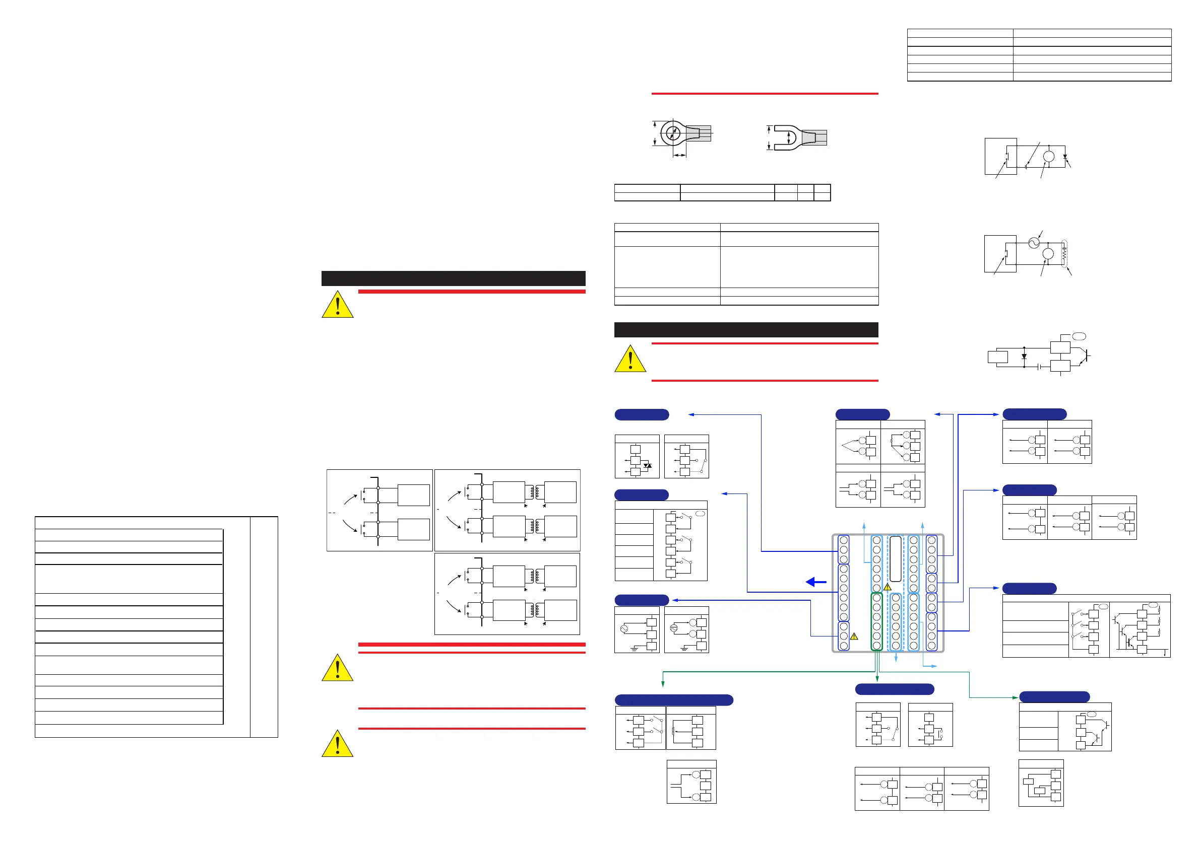
E4-terminal area
E3-terminal area E2-terminal area
PV
HBA
OUT
OUT2
E1-terminal area
PV input
TC input RTD input
Voltage (mV, V) input
A
+
-
+
-
Current (mA) input
+
-
B
b
(Suffix code:
Output 1; -T)
(Option code /HA)
as standard)
Heater break alarm
Heater current detection input
CT1
CT2
COM
External contact output (transistor)
Transistor contact rating: 24 V DC, 50 mA
Heater break alarm-1
output
Heater break alarm-2
output
Common
Control output
101
102
Relay contact output
103
NC
NO
COM
Contact rating: 250 V AC, 3 A
30 V DC, 3 A (resistance load)
101
102
103
104
105
106
107
108
109
110
111
501
502
503
504
505
506
507
508
509
510
511
512
407
401
408
409
410
411
412
301
302
303
304
305
306
307
308
309
310
311
312
201
202
203
204
205
206
207
208
209
210
211
212
Current/voltage pulse output
0-20 mA DC,
4-20 mA DC,
Voltage pulse (12V)
+
-
Retransmission output
+
-
Default: 4-20 mA DC
Default: Undefined
0-20 mA DC,
4-20 mA DC
Cooling-side control output
Relay contact output
NC
NO
COM
Contact rating: 250 V AC, 3 A
30 V DC, 3 A
(resistance load)
101
-112
501
-512
401
-412
301
-312
201
-212
ALM
(Equipped
as standard)
Contact output
External contact output (relay)
AL3
AL2
AL1
Relay contact rating: 240 V AC, 1 A
30 V DC, 1 A (resistance load)
Alarm-3 output
(PV high limit)
Alarm-2 output
( PV low limit)
Alarm-1 output
(PV high limit)
Common
Common
Common
UT
104
105
106
107
108
109
202
203
201
202
203
202
203
203
204
15 V DC loop power supply
14.5-18.0 V DC
(Max. 21 mA DC)
+
-
511
512
510
511
512
507
508
509
511
512
511
512
Factory default: PV input
type is undefined.
OUT
Current/voltage pulse output
0-20 mA DC,
4-20 mA DC,
Voltage pulse (12 V)
+
Retransmission output
+
-
Default: 4-20 mA DC
Default: Undefined
0-20 mA DC,
4-20 mA DC
Control output
(Suffix code: Output 1; -A or -U)
15 V DC loop power supply
14.5-18.0 V DC
(Max. 21 mA DC)
+
-
207
208
207
-
208
207
208
Can be used for retransmission output or 15 V DC loop power supply when
current/voltage pulse output is not used for control output.
Current output range can be changed.
In Position proportional type, can be used for retransmission output or 15 V
DC loop power supply.
RET
Retransmission output
4-20 mA DC or
0-20 mA DC
15 V DC loop power supply
14.5-18.0 V DC
(Max. 21 mA DC)
+
-
+
-
Default: 4-20 mA DC
Default: PV
retransmission
Load resistance 600 Ω or less
Retransmission output
(Option code /RT)
205
206
205
206
Can be used for 15 V DC loop
power supply when not used for
retransmission output.
DI
(Equipped as standard)
Contact input
Contact rating: 12 V DC, 10 mA or more
External contact input
DI3
DI2
DI1
COM
AUTO when DI1=ON
MAN when DI1=OFF
STOP when DI2=ON
RUN when DI2=OFF
Common
DI3
DI2
DI1
COM
+5V
+5V
+5V
No-voltage
contact
Transistor contact
Factory default: No function
UT
UT
209
210
211
212
209
210
211
212
Function can be assigned to the terminals with no function.
VALV
(Suffix code: Output 1=-P)
Position proportional control output
Resistance: 100 Ω to 2.5 kΩ
Feedback input
100%
0%
Relay contact output
HIGH
(direct)
LOW
(reverse)
COM
Contact rating: 250 V AC, 3A
30 V DC, 3 A
(resistance load)
507
508
509
510
511
512
-
Feedback input
Current (mA)
input
When feedback input is current
510
511
512
+
HAL1
HAL2
COM
UT
507
508
509
112
(24 V AC/DC power supply: Option code /DC)
Power supply
100-240 V AC power supply
N
L
Allowable range:
100-240 V AC (+10%/-15%)
(free voltage)
50/60 Hz shared
110
111
24 V AC/DC power supply
-
+
110
111
112
112
N
L
101
102
Triac output
103
NO
COM
Contact rating: 75 - 250 V AC
Allowable load current: 0.8 A
OUT
507
508
Triac output
509
NO
COM
Contact rating: 75 - 250 V AC
Allowable load current: 0.8 A
Triac
(Suffix code:
Output 1; -R or -U)
(Suffix code: Output 2; A or U)
(Suffix code: Output 2; R or U) (Suffix code: Output 2; T)
Wiring direction
6. Terminal Wiring Diagrams
CAUTION
• Do not use an unassigned terminal as the relay terminal.
• Do not use a 100-240 V AC power supply for the 24 V AC/DC
model; otherwise, the instrument will malfunction.
■ UT55A
5. How to Connect Wires
• Wiring work must be carried out by a person with basic electrical
knowledge and practical experience.
• Be sure to turn OFF the power supply to the controller before wiring to
avoid an electric shock. Use a tester or similar device to ensure that no
power is being supplied to a cable to be connected.
• For the wiring cable, the temperature rating is 75 °C or more.
• As a safety measure, always install a circuit breaker (an IEC
60947-compatible product, 5 A, 100 V or 220 V AC) in an easily
accessible location near the instrument. Moreover, provide indication
that the switch is a device for turning off the power to the instrument.
• Install the power cable keeping a distance of more than 1 cm from other
signal wires.
• The power cable is required to meet the IEC standards concerned or the
requirements of the area in which the instrument is being installed.
• WiringshouldbeinstalledtoconformtoNEC(NationalElectricalCode:
ANSI/NFPA-70) or the wiring construction standards in countries or
regions where wiring will be installed.
• Since the insulation provided to each relay output terminal is Functional
insulation, provide Reinforced insulation to the external of the device as
necessary. (Refer to the drawing below.)
This product
Functional
insulation
A safety
voltage circuit
A safety
voltage circuit
This product
Reinforced insulation
Reinforced insulation
Functional
insulation
A hazardous
voltage circuit
A hazardous
voltage circuit
A safety
voltage circuit
A safety
voltage circuit
This product
Reinforced insulation
Reinforced insulation
Functional
insulation
A hazardous
voltage circuit
A hazardous
voltage circuit
A hazardous
voltage circuit
A hazardous
voltage circuit
• When connecting two or more crimp-on terminal lugs to the
single terminal block, bend the crimp-on terminal lugs before
tightening the screw.
• Note that the wiring of two or more crimp-on terminal lugs to the
single high-voltage terminal of the power supply and relay, etc.
does not comply with the safety standard.
• Provide electricity from a single-phase power supply. If the power is
noisy, install an isolation transformer on the primary side, and use a line
filter on the secondary side. When measures against noise are taken, do
not install the primary and secondary power cables close to each other.
• If there is a risk of external lightning surges, use a lightning arrester etc.
• For TC input, use shielded compensating lead wires for wiring. For RTD
input, use shielded wires that have low conductor resistance and cause
no significant differences in resistance between the three wires.
• Since the control output relay has a life span (resistance load of 100,000
times), use the auxiliary relay to perform ON/OFF control.
• The use of inductance (L) loads such as auxiliary relays, motors and
solenoid valves causes malfunction or relay failure; always insert a
CR filter for use with alternating current or a diode for use with direct
current, as a spark-removal surge suppression circuit, into the line in
parallel with the load.
• After completing the wiring, the terminal cover is recommended to use
for the instrument.
● RecommendedCrimp-onTerminalLugs
(F)
3.3
Recommendedtighteningtorque:0.6N·m
Applicablewiresize:Powersupplywiring1.25mm
2
or more
Applicable terminal lug Applicable wire size mm
2
(AWG#) (φd) (A) (F)
M3 0.25to1.65(22to16) 3.3 5.5 4.2
● CableSpecicationsandRecommendedCables
Purpose Name and Manufacturer
Powersupply,relaycontactoutputs 600VGradeheat-resistantPVCinsulatedwires,JISC
3317(HIV),0.9to2.0mm
2
Thermocouple Shieldedcompensatingleadwires,JISC1610
Forthermocoupleinput(PVinputandremoteinputwithdirect
input),shieldedcompensatingleadwireofcross-sectionalarea
lessthanorequalto0.75mm
2
isrecommended.Ifthecross-
sectionalareaiswide,thereferencejunctioncompensation
errormaybelarge.
RTD Shieldedwires(three/fourconductors),UL2482(HitachiCable)
Othersignals(otherthancontactinput/output)
Shielded wires
Othersignals(contactinput/output)
Unshieldedwires
RS-485communication
Shielded wires
Ethernetcommunication
100BASE-TX(CAT-5)/10BASE-T
PROFIBUS-DPcommunication
DedicatedcableforPROFIBUS-DP(Shieldedtwo-wires)
DeviceNetcommunication
DedicatedcableforDeviceNet(Shieldedve-wires)
CC-Linkcommunication
DedicatedcableforCC-Link(Shieldedthree-wires)
PROFIBUS-DP/CC-LinkConnector(wiringside)(Partnumber:A1987JT)
DeviceNetConnector(wiringside)(Partnumber:L4502BW)
Recommendedtighteningtorque:0.5to0.6N·m
DC Relay Wiring
R
External DC power supply
Relay
UT’s contact
Diode
(Mount it directly
to the relay coil
Relay
(Use one with a relay coil rating
less than the UT’s contact rating.)
AC Relay Wiring
UT55A, UT52A
R
CR filter
(Mount it directly
to the relay coil
terminal (socket).)
External AC power supply
Relay
(Use one with a relay coil
rating less than the UT’s
Transistor Output Wiring
+ –
DO
Load
COM

 Loading...


