IM 05P01C31-15EN page 10/12
IfyouareusingtwoormoregroupsofPIDparameters,usethefollowingtabletorecordtheirsetting values.
Parameter n=2 n=3 n=4 n=5 n=6 n=7 n=8 R
P
I
D
OH
OL
MR
HYS
SU.HY
HY.UP
HY.LO
DR
SU.DR
Pc
Ic
Dc
OHc
OLc
HYSc
DB
PO
SU.PO
POc
n:groupnumber
■ Tuning Parameter
Menusymbol:
(TUNE)
Parameter
symbol
Name of Parameter Setting Range
Initial
value
User
setting
Display
level
(SC)
Super function
OFF:Disable
1:Overshootsuppressingfunction
(normalmode)
2:Huntingsuppressingfunction
(stablemode)
Enablestoanswerthewider
characteristicchangescompared
with response mode.
3:Huntingsuppressingfunction
(responsemode)
Enablesquickfollow-upandshort
convergingtimeofPVforthe
changedSP.
4:Overshootsuppressingfunction
(strongsuppressingmode)
Note:Setpoints2and3mustbe
usedinPIDcontrolorPIcontrol.
Disabledinthefollowingcontrols:
1)ON/OFFcontrol,2)PDcontrol,3)
Pcontrol,4)Heating/coolingcontrol.
Donotusethefunctionforthecon-
trol processes with response such as
oworpressurecontrol.
OFF EASY
(AT.TY)
Auto-tuningtype
0:Normal
1:Stability
0 STD
(STM)
Sample PI sampled time 0to9999s 60s
EASY
(SWD)
Sample PI control time
span
0to9999s 30s
(AR)
Anti-resetwindup
(excessintegration
prevention)
AUTO,50.0to200.0% AUTO
STD
(OPR)
Outputvelocitylimiter
OFF:Disable
0.1to100.0%/s
OFF
(MPON)
Manual preset output
numberselection
SelecttheoutputusedinMANmode
whenswitchedfromAUTOtoMAN
mode.
OFF:HoldthecontroloutputinAUTO
mode(bumpless)
1:Usemanualpresetoutput1(output
bump)
2:Usemanualpresetoutput2(output
bump)
3:Usemanualpresetoutput3(output
bump)
4:Usemanualpresetoutput4(output
bump)
5:Usemanualpresetoutput5(output
bump)
OFF
to
(MPO1toMPO5)
Manual preset output 1
to 5
-5.0to105.0%
However,outputislimitedtothe
outputhighlimitandlowlimit.
0.0%
Table
below
Usethefollowingtabletorecordthemanualpresetoutputsettingvalue.
Parameter n=1 n=2 n=3 n=4 n=5
MPOn
■ Zone Control Parameter
Menusymbol: (ZONE)
Parameter
symbol
Name of Parameter Setting Range
Initial
value
User
setting
Display
level
to
(RP1toRP7)
Referencepoint1to7
Set reference points at which switch-
ingiscarriedoutbetweengroupsof
PIDconstantsaccordingtothegiven
temperaturezone.
0.0to100.0%ofPVinputrange(EU)
(RP1≤RP2≤RP3≤RP4≤RP5≤
RP6≤RP7)
100.0%
ofPV
input
range
Table
below
STD
(RHY)
ZonePIDswitching
hysteresis
Hysteresiscanbesetforswitchingat
a reference point.
0.0to10.0%ofPVinputrangespan
(EUS)
0.5%
ofPV
input
range
span
(RDV)
Referencedeviation
SetadeviationfromSP.ThePIDfor
referencedeviationisusedifthere
isalargerdeviationthanthepreset
referencedeviation.
OFF:Disable
0.0+1digitto100.0%ofPVinput
rangespan(EUS)
OFF
ForZonecontrol,setthesetupparameterZON(zonePIDselection)toZonePIDse-
lection.
Usethefollowingtabletorecordthereferencepointsettingvalue.
Parameter n=1 n=2 n=3 n=4 n=5 n=6 n=7
RPn
■ P Parameter (for Ladder Program)
Menusymbol: (PPAR)
Parameter
symbol
Name of Parameter Setting Range
Initial
value
User
setting
Display
level
to
(P01toP10)
P01toP10parameter
-19999to30000(Setadecimalpoint
positionusingLL50AParameterSet-
tingSoftware.)
0
Table
below
STD
Parameter n=01 n=02 n=03 n=04 n=05 n=06 n=07 n=08 n=09 n=10
Pn
■ 10-segment Linearizer-1, -2 Setting Parameter
Menusymbol: (PYS1)
(PYS2)
Parameter
symbol
Name of Parameter Setting Range
Initial
value
User
setting
Display
level
(PYS)
10-segmentlinearizer
selection
OFF:Disable
PV:PVanaloginput
RSP:RSPanaloginput
AIN2:AIN2analoginput
AIN4:AIN4analoginput
PVIN:PVinput
OUT:OUTanalogoutput
OUT2:OUT2analogoutput
RET:RETanalogoutput
PV
(CTLM
:
SGL)
STD
(A1)
10-segmentlinearizer
input 1
-66.7to105.0%ofinputrange(EU)
Outputlinearizer:-5.0to105.0%
0.0%
(B1)
10-segmentlinearizer
output 1
10-segmentlinearizerbias:-66.7to
105.0%ofinputrangespan(EUS)
10-segmentlinearizerapproximation:
-66.7to105.0%ofinputrange(EU)
Outputlinearizer:-5.0to105.0%
0.0%
to
to
(A2toA11,
B2toB11)
10-segmentlinearizer
input 2 to 11
10-segmentlinearizer
output 2 to 11
SameasA1andB1
Same
as
A1
and
B1
(PMD)
10-segmentlinearizer
mode
0:10-segmentlinearizerbias
1:10-segmentlinearizerapproxima-
tion
0
Usethefollowingtabletorecordthe10-segmentlinearizerinputandoutputsettingvalues.
Parameter n=2 n=3 n=4 n=5 n=6 n=7 n=8 n=9 n=10 n =11
An
Bn
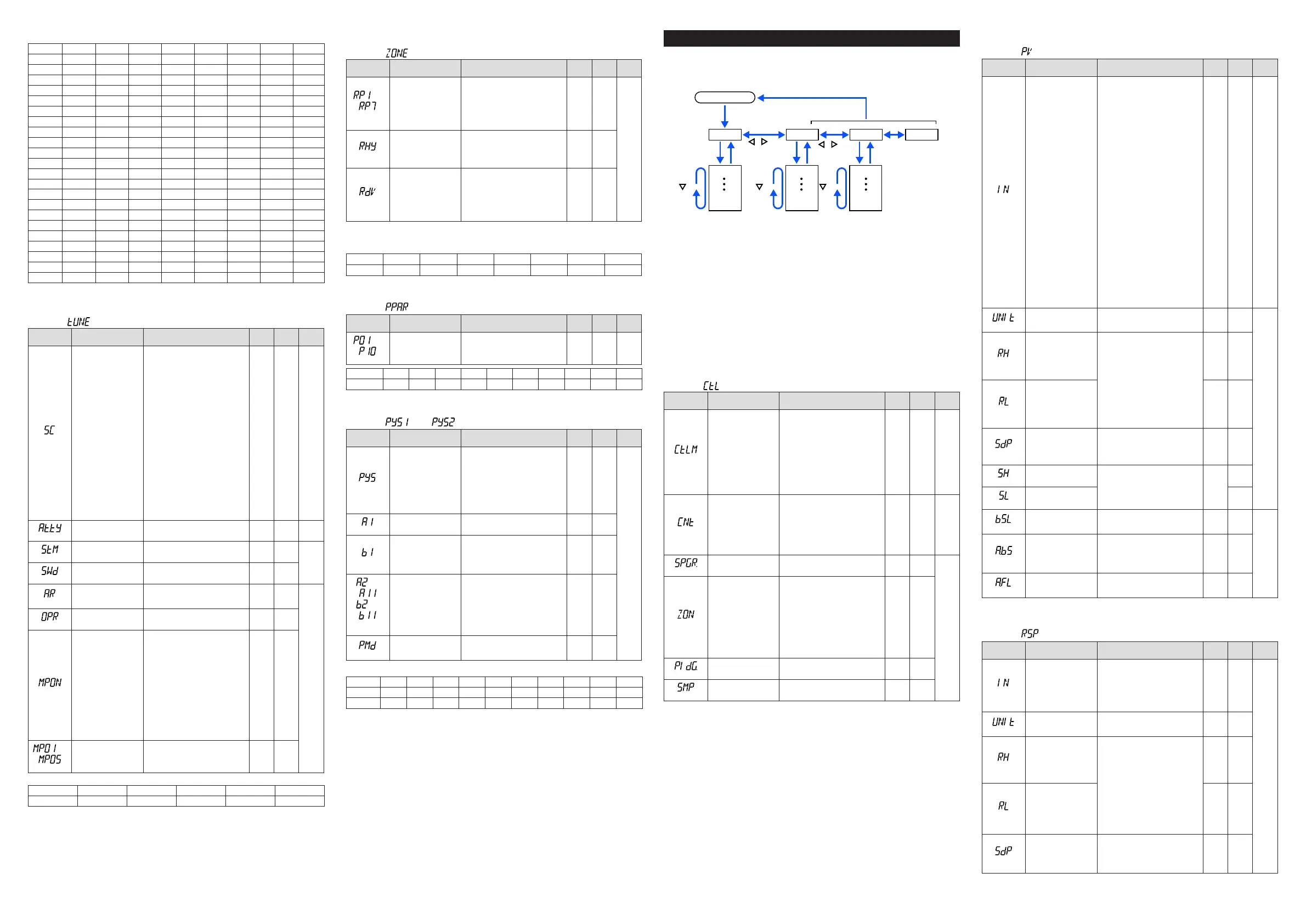
Setup Parameters
HolddownthePARAMETERkeyorPARAkeyandLeftarrowkeysimultaneouslyfor3
secondstomovefromtheOperationDisplayorOperationParameterSettingDisplayto
theSetupParameterSettingDisplay.
PresstheDISPLAYkeyorDISPkeyoncetoreturntotheOperationDisplay.
Menu
DISPLAY key
or DISP key
PARAMETER key
or PARA key
key key key
key
key
Operation Dsipaly
Parameter
Parameter
Parameter
Parameter
Parameter
Parameter
END
Menu
END
Menu END
END
Menu Display and
Parameter Setting
Display are changed
in a circular pattern.
Move to the Operation Parameter Setting Display:
Hold down the PARAMETER key or PARA key for 3 sec.
Hold down PARAMETER key or PARA key and
Left arrow key simultaneously for 3 sec.
Operation for Setting
· Toselecttheparametersettingdisplayedastheinitialvalue,presstheDownarrow
keytomovetothenextparameter.
· Tochangeandsettheparametersetting,presstheSET/ENTERkeytostarttheset-
pointblinking.Theblinkingstateallowsyoutomakechanges(settingmode).Usethe
Up/Down/Left/Rightarrowkeystochangethesetpoint.PresstheSET/ENTERkeyto
registerthesetting.
Notethatthereare someparameterswhich arenotdisplayeddependingontheModel
andSufxcodes,controlmode(CTLM),controltype(CNT),etc.Theparametersforpro-
fessional
settingmode(LEVL:PRO)arenotdescribedinthismanual.SeeUser’sManual
(IM05P01C31-01EN).
■ Control Function Setting Parameter
Menusymbol: (CTL)
Parameter
symbol
Name of Parameter Setting Range
Initial
value
User
setting
Display
level
(CTLM)
Controlmode
Whenusingthecontrolsotherthan
Single-loopcontrol,seeUser'sManu-
al(IM05P01C31-01EN).
SGL STD
SGL:Single-loopcontrol
CAS1:Cascadeprimary-loopcontrol
CAS2:Cascadesecondary-loopcontrol
CAS:Cascadecontrol
BUM:Loopcontrolforbackup
PVSW:LoopcontrolwithPVswitching
PVSEL:LoopcontrolwithPVauto-selector
PVHD:LoopcontrolwithPV-holdfunction
(CNT)
Controltype
PID:PIDcontrol
ONOF:ON/OFFcontrol(1pointofhysteresis)
ONOF2:ON/OFFcontrol(2pointsofhysteresis)
2P2L:Two-positiontwo-levelcontrol
H/C:Heating/coolingcontrol
S-PI:SamplePIcontrol
BATCH:BatchPIDcontrol
FFPID:Feedforwardcontrol
PIDor
H/C(for
Heat-
ing/
Coo-
ling-
type)
EASY
(SPGR.)
NumberofSPgroups
SetanumberofSPgroupstouse.
1to8
8
STD
(ZON)
ZonePIDselection
Ifsetto“SPgroupnumberselection,”allows
PIDconstantstobeselectedforeachSP
group.
If
setto“ZonePIDselection,”automatically
selectsPIDconstantsaccordingtotherange
setintheReferencepoint.
0:SPgroupnumberselection1
1:ZonePIDselection(selectionbyPV)
2:ZonePIDselection(selectionbytargetSP)
3:SPgroupnumberselection2
4:ZonePIDselection(selectionbySP)
0
(PIDG.)
NumberofPIDgroups
SetanumberofPIDgroupstouse.
1to8
8
(SMP)
Inputsamplingperiod
(controlperiod)
50:50ms,100:100ms,200:200ms 100
■ PV Input Setting Parameter
Menusymbol: (PV)
Parameter
symbol
Name of Parameter Setting Range
Initial
value
User
setting
Display
level
(IN)
PVinputtype
OFF:Disable
K1:-270.0to1370.0
0
C/-450.0to2500.0
0
F
K2:-270.0to1000.0
0
C/-450.0to2300.0
0
F
K3:-200.0to500.0
0
C/-200.0to1000.0
0
F
J:-200.0to1200.0
0
C/-300.0to2300.0
0
F
T1:-270.0to400.0
0
C/-450.0to750.0
0
F
T2:0.0to400.0
0
C/-200.0to750.0
0
F
B:0.0to1800.0
0
C/32to3300
0
F
S:0.0to1700.0
0
C/32to3100
0
F
R:0.0to1700.0
0
C/32to3100
0
F
N:-200.0to1300.0
0
C/-300.0to2400.0
0
F
E:-270.0to1000.0
0
C/-450.0to1800.0
0
F
L:-200.0to900.0
0
C/-300.0to1600.0
0
F
U1:-200.0to400.0
0
C/-300.0to750.0
0
F
U2:0.0to400.0
0
C/-200.0to1000.0
0
F
W:0.0to2300.0
0
C/32to4200
0
F
PL2:0.0to1390.0
0
C/32.0to2500.0
0
F
P2040:0.0to1900.0
0
C/32to3400
0
F
WRE:0.0to2000.0
0
C/32to3600
0
F
JPT1:-200.0to500.0
0
C/-300.0to1000.0
0
F
JPT2:-150.0to150.0
0
C/-200.0to300.0
0
F
PT1:-200.0to850.0
0
C/-300.0to1560.0
0
F
PT2:-200.0to500.0
0
C/-300.0to1000.0
0
F
PT3:-150.00to150.00
0
C/-200.0to300.0
0
F
0.4-2V:0.400to2.000V
1-5V:1.000to5.000V
4-20:4.00to20.00mA
0-2V:0.000to2.000V
0-10V:0.00to10.00V
0-20:0.00to20.00mA
-1020:-10.00to20.00mV
0-100:0.0to100.0mV
OFF EASY
(UNIT)
PVinputunit
-:Nounit,C:DegreeCelsius
-:Nounit,--:Nounit,---:Nounit,
F:DegreeFahrenheit
C
(RH)
MaximumvalueofPV
inputrange
Dependsontheinputtype.
-Fortemperatureinput-
Setthetemperaturerangethatis
actuallycontrolled.(RL<RH)
-Forvoltage/currentinput-
Settherangeofavoltage/current
signalthatisapplied.
Thescaleacrosswhichthevoltage/
currentsignalisactuallycontrolled
shouldbesetusingthemaximum
valueofinputscale(SH)andmini-
mumvalueofinputscale(SL).
(Inputisalways0%whenRL=RH.)
Depends
on the
input type
(RL)
MinimumvalueofPV
inputrange
Depends
on the
input type
(SDP)
PVinputscaledecimal
point position
0:Nodecimalplace
1:Onedecimalplace
2:Twodecimalplaces
3:Threedecimalplaces
4:Fourdecimalplaces
Depends
on the
input type
(SH)
MaximumvalueofPV
input scale
-19999to30000,(SL<SH),
|SH-SL|≤30000
Depends
on the
input type
(SL)
MinimumvalueofPV
input scale
(BSL)
PVinputburnoutaction
OFF:Disable
UP:Upscale
DOWN:Downscale
Depends
on the
input type
STD
(A.BS)
PVanaloginputbias
-100.0to100.0%ofPVinputrange
span(EUS)
0.0%of
PVinput
range
span
(A.FL)
PVanaloginputlter
OFF,1to120s
OFF
W:W-5%Re/W-26%Re(HoskinsMfg.Co.).ASTME988,WRE:W97Re3-W75Re25
■ RSP Input Setting Parameter (E1-terminal Area)
Menusymbol: (RSP)
Parameter
symbol
Name of Parameter Setting Range
Initial
value
User
setting
Display
level
(IN)
RSPremoteinputtype
0.4-2V:0.400to2.000V
-5V:1.000to5.000V
0-2V:0.000to2.000V
0-10V:0.00to10.00V
0-125:0.000to1.250V
Foroption/U1,RSPremoteinput
typeissameasPVinputtype
1-5V
EASY
(UNIT)
RSPremoteinputunit
-:Nounit,C:DegreeCelsius
-:Nounit,--:Nounit,---:Nounit,
F:DegreeFahrenheit
C
(RH)
MaximumvalueofRSP
remoteinputrange
Dependsontheinputtype.
-Fortemperature(/U1option)input-
Setthetemperaturerangethatis
actuallycontrolled.(RL<RH)
-Forvoltage/current(/U1option)input
Settherangeofavoltage/current
signalthatisapplied.
Thescaleacrosswhichthevoltage/
currentsignalisactuallycontrolled
shouldbesetusingthemaximum
valueofinputscale(SH)and
minimumvalueofinputscale(SL).
(Inputisalways0%whenRL=RH.)
Depends
on the
input type
(RL)
MinimumvalueofRSP
remoteinputrange
Depends
on the
input type
(SDP)
RSPremoteinputscale
decimal point position
0:Nodecimalplace
1:Onedecimalplace
2:Twodecimalplaces
3:Threedecimalplaces
4:Fourdecimalplaces
Depends
on the
input type

 Loading...


