IM 05P01C31-15EN page 11/12
(SH)
MaximumvalueofRSP
remote input scale
-19999to30000,(SL<SH),
|SH-SL|≤30000
Depends
on the
input type
EASY
(SL)
MinimumvalueofRSP
remote input scale
(BSL)
RSPremoteinputburn-
out action
OFF:Disable
UP:Upscale
DOWN:Downscale
Depends
on the
input type
STD
(RTD.S)
RTDwiringsystem
3-W:3-wiresystem
4-W:4-wiresystem
(TheLL50AParameterSettingSoft-
wareisrequiredtouseRSPterminals
inputasPV.)
3-W
■ AIN2/AIN4 Aux. Analog Input Setting Parameter
(E2/E4-terminal Area)
Menusymbol: (AIN2)
(AIN4)
Parameter
symbol
Name of Parameter Setting Range
Initial
value
User
setting
Display
level
(IN)
AIN2/AIN4aux.analog
input type
0.4-2V:0.400to2.000V
1-5V:1.000to5.000V
0-2V:0.000to2.000V
0-10V:0.00to10.00V
0-125:0.000to1.250V
1-5V
EASY
(UNIT)
AIN2/AIN4aux.analog
input unit
-:Nounit
C:DegreeCelsius
-:Nounit
--:Nounit
---:Nounit
F:DegreeFahrenheit
C
(RH)
MaximumvalueofAIN2/
AIN4aux.analoginput
range
Dependsontheinputtype.
Settherangeofavoltagesignalthat
is applied.
Thescaleacrosswhichthevoltage
signalisactuallycontrolledshouldbe
setusingthemaximumvalueofinput
scale(SH)andminimumvalueof
inputscale(SL).
(Inputisalways0%whenRL=RH.)
Depends
on the
input type
(RL)
MinimumvalueofAIN2/
AIN4aux.analoginput
range
Depends
on the
input type
(SDP)
AIN2/AIN4aux.analog
input scale decimal point
position
0:Nodecimalplace
1:Onedecimalplace
2:Twodecimalplaces
3:Threedecimalplaces
4:Fourdecimalplaces
Depends
on the
input type
(SH)
MaximumvalueofAIN2/
AIN4aux.analoginput
scale
-19999to30000,(SL<SH),
|SH-SL|≤30000
Depends
on the
input type
(SL)
MinimumvalueofAIN2/
AIN4aux.analoginput
scale
Depends
on the
input type
(BSL)
AIN2/AIN4aux.analog
inputburnoutaction
OFF:Disable
UP:Upscale
DOWN:Downscale
Depends
on the
input type
STD
■ Input Range, SP Limiter Setting Parameter
Menusymbol: (MPV)
Parameter
symbol
Name of Parameter Setting Range
Initial
value
User
setting
Display
level
(P.UNI)
ControlPVinputunit
-:Nounit
C:DegreeCelsius
-:Nounit
--:Nounit
---:Nounit
F:DegreeFahrenheit
Same
asPV
input
unit
STD
(P.DP)
ControlPVinputdecimal
point position
0:Nodecimalplace
1:Onedecimalplace
2:Twodecimalplaces
3:Threedecimalplaces
4:Fourdecimalplaces
Depends
on the
input type
(P.RH)
Maximumvalueof
controlPVinputrange
-19999to30000,(P.RL<P.RH),
|P.RH-P.RL|≤30000
Depends
on the
input type
(P.RL)
Minimumvalueofcontrol
PVinputrange
Depends
on the
input type
(SPH)
SPhighlimit
0.0to100.0%ofPVinputrange(EU),
(SPL<SPH)
100.0%
ofPV
input
range
(SPL)
SP low limit
0.0%
ofPV
input
range
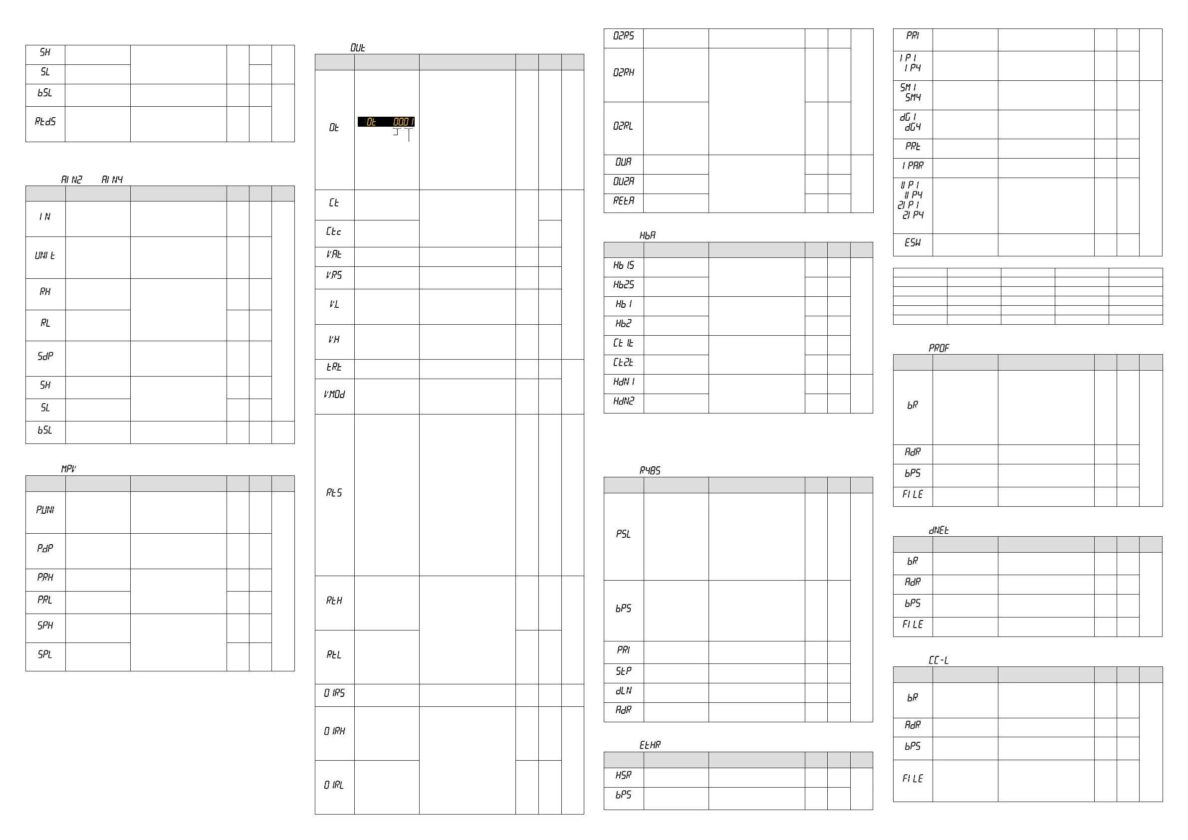
■ Output Setting Parameter
Menusymbol: (OUT)
Parameter
symbol
Name of Parameter Setting Range
Initial
value
User
setting
Display
level
(OT)
Outputtypeselection
Upper two
digits
Lower two
digits
ControloutputorHeating-sidecontrol
output(Lowertwodigits)
00:OFF
01:OUTterminals(voltagepulse)
02:OUTterminals(current)
03:OUTterminals(relay/triac)
04:OUT2terminals(voltagepulse)
05:OUT2terminals(current)
06:OUT2terminals(relay/triac)
Cooling-sidecontroloutput(Upper
twodigits)
00:OFF
01:OUTterminals(voltagepulse)
02:OUTterminals(current)
03:OUTterminals(relay/triac)
04:OUT2terminals(voltagepulse)
05:OUT2terminals(current)
06:OUT2terminals(relay/triac)
Standard
type:
00.03
Heating/
cooling
type:
06.03
EASY
(CT)
Controloutputcycletime
Heating-sidecontrol
outputcycletime(in
Heating/coolingcontrol)
0.5to1000.0s 30.0s
EASY
(CTc)
Cooling-sidecontrol
output cycle time
(V.AT)
Automaticvalveposition
adjustment
OFF:Stopautomaticadjustment
ON:Startautomaticadjustment
OFF
(V.RS)
Valvepositionsetting
reset
SettingV.RStoONresetsthevalve
adjustmentsettingsandcausesthe
indication“V.RS”toblink.
OFF
(V.L)
Fully-closedvalveposi-
tionsetting
PressingtheSET/ENTERkeywithvalve
positionsettothefully-closedposition
byDownarrowkeycausestheadjusted
valuetobestored.WhenV.Ladjustment
iscomplete,V.Lstopsblinking.
-
(V.H)
Fully-openedvalveposi-
tionsetting
PressingtheSET/ENTERkeywithvalve
positionsettothefully-openedpositionby
Uparrowkeycausestheadjustedvalue
tobestored.WhenV.Hadjustmentis
complete,V.Hstopsblinking
-
(TR.T)
Valvetravelingtime 5to300s 60s
STD
(V.MOD)
Valveadjustingmode
0:Valvepositionfeedbacktype
1:Valvepositionfeedbacktype
(movestotheestimatingtypeifa
feedbackinputerrororbreakoccurs.)
2:Valvepositionestimatingtype
0
(RTS)
Retransmissionoutput
typeofRET
OFF:Disable
PV1:PV
SP1:SP
OUT1:OUT(Valveopening:0to100
%inPositionproportionalcontrol)
LPS:15VDClooppowersupply
PV2:Loop-2PV
SP2:Loop-2SP
OUT2:Loop-2OUT
TSP1:TargetSP
HOUT1:Heating-sideOUT
COUT1:Cooling-sideOUT
MV1:Positionproportionaloutput
(internalcomputedvalue)
TSP2:Loop-2targetSP
HOUT2:Loop-2heating-sideOUT
COUT2:Loop-2cooling-sideOUT
MV2:Loop-2positionproportional
output(internalcomputedvalue)
PV:PVterminalsanaloginput
RSP:RSPterminalsanaloginput
AIN2:AIN2terminalsanaloginput
AIN4:AIN4terminalsanaloginput
*Loop-2settingvaluesare
unavailable
inSingle-loopcontrol.
PV1 EASY
(RTH)
Maximumvalueof
retransmission output
scaleofRET
WhenRTS=PV1,SP1,PV2,SP2,TSP1,
TSP2,PV,RSP,AIN2,orAIN4,RTL+1
digitto30000-19999toRTH-1digit
Decimalpointposition:
WhenRTS=PV1,SP1,orTSP1,decimal
pointpositionissameasthatofPVinput.
WhenRTS=PV2,SP2,orTSP2,decimal
pointpositionissameasthatofRSPinput.
WhenRTS=PV,decimalpointpositionis
sameasthatofPVinputscale.
WhenRTS=RSP,decimalpointposition
issameasthatofRSPinputscale.
WhenRTS=AIN2,decimalpointposition
issameasthatofAIN2scale.
WhenRTS=AIN4,decimalpointposition
issameasthatofAIN4scale.
100%
ofPV
input
range
STD
(RTL)
Minimumvalueof
retransmission output
scaleofRET
0%
ofPV
input
range
(O1RS)
Retransmissionoutput
typeofOUTcurrentoutput
SameasRTS
OFF
STD
(O1RH)
Maximumvalueof
retransmission output
scaleofOUTcurrent
output
WhenO1RS=PV1,SP1,PV2,SP2,
TSP1,TSP2,PV,RSP,AIN2,orAIN4,O1RL
+1digitto30000-19999toO1RH-1digit
Decimalpointposition:
WhenO1RS=PV1,SP1,orTSP1,decimal
pointpositionissameasthatofPVinput.
WhenO1RS=PV2,SP2,orTSP2,decimal
pointpositionissameasthatofRSPinput.
WhenO1RS=PV,decimalpointpositionis
sameasthatofPVinputscale.
WhenO1RS=RSP,decimalpointposition
issameasthatofRSPinputscale.
WhenO1RS=AIN2,decimalpointposition
issameasthatofAIN2scale.
WhenO1RS=AIN4,decimalpointposition
issameasthatofAIN4scale
-
STD
(O1RL)
Minimumvalueof
retransmission output
scaleofOUTcurrent
output
-
(O2RS)
Retransmissionoutputtype
ofOUT2currentoutput
SameasRTS
OFF
STD
(O2RH)
Maximumvalueof
retransmission output
scaleofOUT2current
output
WhenO2RS=PV1,SP1,PV2,SP2,
TSP1,TSP2,PV,RSP,AIN2,orAIN4,O2RL
+1digitto30000-19999toO2RH-1digit
Decimalpointposition:
WhenO2RS=PV1,SP1,orTSP1,decimal
pointpositionissameasthatofPVinput.
WhenO2RS=PV2,SP2,orTSP2,decimal
pointpositionissameasthatofRSPinput.
WhenO2RS=PV,decimalpointpositionis
sameasthatofPVinputscale.
WhenO2RS=RSP,decimalpointposition
issameasthatofRSPinputscale.
WhenO2RS=AIN2,decimalpointposition
issameasthatofAIN2scale.
WhenO2RS=AIN4,decimalpointposition
issameasthatofAIN4scale.
-
(O2RL)
Minimumvalueof
retransmission output
scaleofOUT2current
output
-
(OU.A)
OUTcurrentoutput
range
4-20:4to20mA
0-20:0to20mA
20-4:20to4mA
20-0:20to0mA
4-20
STD
(OU2.A)
OUT2currentoutput
range
4-20
(RET.A)
RETcurrentoutput
range
4-20
■ Heater Break Alarm Setting Parameter
Menusymbol: (HBA)
Parameter
symbol
Name of Parameter Setting Range
Initial
value
User
setting
Display
level
(HB1.S)
Heaterbreakalarm-1
function selection
0:Heatercurrentmeasurement
1:Heaterbreakalarm
1
EASY
(HB2.S)
Heaterbreakalarm-2
function selection
1
(HB1)
Heaterbreakalarm-1
current setpoint
OFF,0.1to300.0Arms
OFF
(HB2)
Heaterbreakalarm-2
current setpoint
OFF
(CT1.T)
CT1
coilwindingnumberratio
1to3300
800
(CT2.T)
CT2
coilwindingnumberratio
800
(HDN1)
Heaterbreakalarm-1
On-delaytimer
0.00to99.59(m.s)
0.00
STD
(HDN2)
Heaterbreakalarm-2
On-delaytimer
0.00
IncaseswherethecurrenttransformersmanufacturedbyU.R.D.Co.,Ltdareused,set
thefollowingvalueforthecoilwindingnumberratio.
CTL-6-S-H:800
CTL-12L-30:3000
■
RS-485 Communication Setting Parameter (E1/E3/E4-terminal Area)
Menusymbol: (R485)
Parameter
symbol
Name of Parameter Setting Range
Initial
value
User
setting
Display
level
(PSL)
Protocol selection
PCL:PClinkcommunication
PCLSM:PClinkcommunication(with
checksum)
LADR:Laddercommunication
CO-M:Coordinatedmasterstation
CO-S:Coordinatedslavestation
MBASC:Modbus(ASCII)
MBRTU:Modbus(RTU)
CO-S1:Coordinatedslavestation
(Loop-1mode)
CO-S2:Coordinatedslavestation
(Loop-2mode)
P-P:Peer-to-peercommunication
MBRTU
EASY
(BPS)
Baud rate
600:600bps
1200:1200bps
2400:2400bps
4800:4800bps
9600:9600bps
19200:19.2kbps
38400:38.4kbps
*ThebaudrateforRS-485isupto
19.2kbpsinE4-terminalarea.
19200
(PRI)
Parity
NONE:None
EVEN:Even
ODD:Odd
EVEN
(STP)
Stopbit 1:1bit,2:2bits 1
(DLN)
Datalength 7:7bits,8:8bits 8
(ADR)
Address 1to99 1
■
Ethernet Communication Setting Parameter (E3-terminal Area)
Menusymbol: (ETHR)
Parameter
symbol
Name of Parameter Setting Range
Initial
value
User
setting
Display
level
(HSR)
High-speedresponsemode
OFF,1to8 1
EASY
(BPS)
Baud rate
9600:9600bps
19200:19.2kbps
38400:38.4kbps
38400
(PRI)
Parity
NONE:None
EVEN:Even
ODD:Odd
EVEN
EASY
to
(IP1toIP4)
IP address 1 to 4
0to255
Initialvalue:(IP1).(IP2).(IP3).(IP4)=
(192).(168).(1).(1)
See left
Table
below
to
(SM1toSM4)
Subnetmask1to4
0to255
Initialvalue:
(SM1).(SM2).(SM3).(SM4)
=(255).(255).(255).(0)
See left
Table
below
EASY
to
(DG1toDG4)
Defaultgateway1to4
0to255
Initialvalue:
(DG1).(DG2).(DG3).(DG4)=
(0).(0).(0).(0)
See left
Table
below
(PRT)
Portnumber 502,1024to65535 502
(IPAR)
IP access restriction OFF:Disable,ON:Enable OFF
to
,
to
(1.IP1to1.IP4,
2.IP1to2.IP4)
PermittedIPaddress1-1
to1-4
PermittedIPaddress2-1
to2-4
0to255
Initialvalue:
(1.IP1).(1.IP2).(1.IP3).(1.IP4)=
(255).(255).(255).(255)
(2.IP1).(2.IP2).(2.IP3).(2.IP4)=
(255).(255).(255).(255)
See left
Table
below
(ESW)
Ethernetsettingswitch
Settingthisparameterto“ON”
enablestheEthernetcommunication
parametersettings.OFF,ON
OFF
UsethefollowingtabletorecordEthernetcommunicationsettingvalue.
Parameter n=1 n=2 n=3 n=4
IPn
SMn
DGn
1.IPn
2.IPn
■
PROFIBUS-DP Communication Setting Parameter (E3-terminal Area)
Menusymbol: (PROF)
Parameter
symbol
Name of Parameter Setting Range
Initial
value
User
setting
Display
level
(BR)
Baud rate
9.6K:9.6kbps
19.2K:19.2kbps
93.75K:93.75kbps
187.5K:187.5kbps
0.5M:0.5Mbps
1.5M:1.5Mbps
3M:3Mbps
6M:6Mbps
12M:12Mbps
AUTO
45.45K:45.45kbps
AUTO
EASY
(ADR)
Address 0to125 3
(BPS)
Baud rate
9600:9600bps
19200:19.2kbps
38400:38.4kbps
38400
(FILE)
Prolenumber 0to5 0
■
DeviceNet Communication Setting Parameter (E3-terminal Area)
Menusymbol: (DNET)
Parameter
symbol
Name of Parameter Setting Range
Initial
value
User
setting
Display
level
(BR)
Baud rate
125K:125kbps
250K:250kbps
500K:500kbps
125K
EASY
(ADR)
Address 0to63 63
(BPS)
Baud rate
9600:9600bps
19200:19.2kbps
38400:38.4kbps
38400
(FILE)
Prolenumber 0to5 0
■
CC-Link Communication Setting Parameter (E3-terminal Area)
Menusymbol: (CC-L)
Parameter
symbol
Name of Parameter Setting Range
Initial
value
User
setting
Display
level
(BR)
Baud rate
156K:156kbps
625K:625kbps
2.5K:2.5kbps
5M:5Mbps
10M:10Mbps
10M
EASY
(ADR)
Address 1 to 64 3
(BPS)
Baud rate
9600:9600bps
19200:19.2kbps
38400:38.4kbps
38400
(FILE)
Prolenumber
UT55A:0to7
(0,1and6:Ver.1.10)(2to5and7:
Ver.2.00)
UT52A:0to3and6
(0,1and6:Ver.1.10)(2and3:
Ver.2.00)
0
SetupParameters(Continuedfrompage10)
■
RSP Input Setting Parameter (E1-terminal Area) (Continued)

 Loading...


