IM 05P01C31-15EN page 12/12
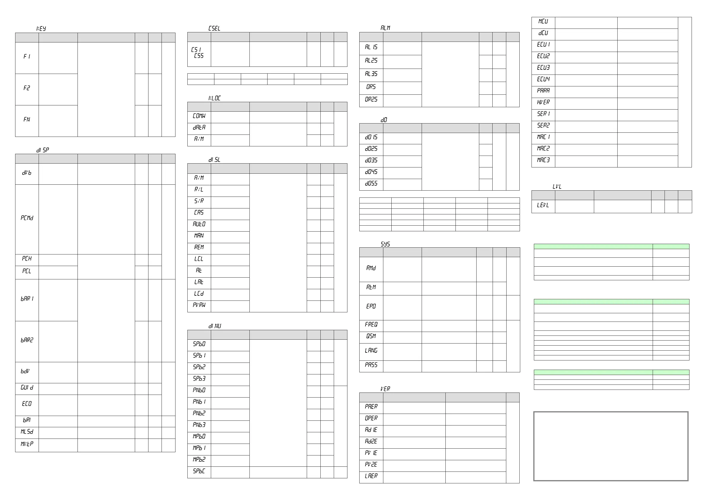
■KeyActionSettingParameter
Menusymbol: (KEY)
Parameter
symbol
Name of Parameter Setting Range
Initial
value
User
setting
Display
level
(F1)
Userfunctionkey-1ac-
tionsetting
OFF:Disable
A/M:AUTO/MANswitch
C/A/M:CAS/AUTO/MANswitch
R/L1:REM/LCLswitch
R/L2:Loop-2REM/LCLswitch
S/R:STOP/RUNswitch
CAS:SwitchtoCAS
AUTO:SwitchtoAUTO
MAN:SwitchtoMAN
REM1:SwitchtoREM
LCL1:SwitchtoLCL
REM2:SwitchtoLoop-2REM
LCL2:SwitchtoLoop-2LCL
STOP:SwitchtoSTOP
RUN:SwitchtoRUN
AT:Auto-tuning
LTUP:LCDbrightnessUP
LTDN:LCDbrightnessDOWN
BRI:AdjustLCDbrightness
LCD:LCDbacklightON/OFFswitch
LAT:Latchrelease
PID:PIDtuningswitch
*Loop-2settingvaluesare
unavailableinSingle-loopcontrol.
OFF
EASY
(F2)
Userfunctionkey-2ac-
tionsetting
OFF
(Fn)
Userfunctionkey-nac-
tionsetting
PID
■DisplayFunctionSettingParameter
Menusymbol: (DISP)
Parameter
symbol
Name of Parameter Setting Range
Initial
value
User
setting
Display
level
(DVB)
Deviationdisplayband
Permitsachangeinthespanof
deviationshownonthefront-panel
deviationmonitor.
DisplayedonlyforUT55A.
0.0to100.0%ofPVinputrangespan(EUS).
1.0%
ofPV
input
range
span
STD
(PCMD)
ActivecolorPVdisplay
switch
0:Fixedinwhite
1:Fixedinred
2:Linktoalarm1(AlarmOFF:white,
AlarmON:red)
3:Linktoalarm1(AlarmOFF:red,
AlarmON:white)
4:Linktoalarm1or2(AlarmOFF:
white,AlarmON:red)
5:Linktoalarm1or2(AlarmOFF:
red,AlarmON:white)
6:PVlimit(Withinrange:white,Out
ofrange:red)
7:PVlimit(Withinrange:red,Outof
range:white)
8:SPdeviation(Withindeviation:
white,Outofdeviation:red)
9:SPdeviation(Withindeviation:red,
Outofdeviation:white)
10:LinktoDI(ON:red,OFF:white)
0
EASY
(PCH)
PVcolorchangehigh
limit
SetadisplayvaluewheninPVlimit
orSPdeviation.
-19999to30000(Setavaluewithin
theinputrange.)
Decimalpointpositiondependson
the input type.
0
(PCL)
PVcolorchangelowlimit 0
(BAR1)
Upperbar-graphdisplay
registration
0:Disable
1:
OUT,Heating-sideOUT,Internalvalue
in Position proportional control
2:Cooling-sideOUT
3:PV
4:SP
5:Deviation
6:
Loop-2OUT,Loop-2heating-sideOUT
7:Loop-2cooling-sideOUT
8:Loop-2PV
9:Loop-2SP
10:Loop-2deviation
11to16:Disable
17:Feedbackinput(valveopening)
18:PVterminalsanaloginput
19:RSPterminalsanaloginput
20:AIN2terminalsanaloginput
21:AIN4terminalsanaloginput
27:TSP
28:TSPdeviation
29:Loop-2TSP
30:Loop-2TSPdeviation
5
(Heating
/cooling
type:1)
STD
(BAR2)
Lowerbar-graphdisplay
registration
1
(Heating
/cooling
type:2)
(Posi
-
tion
propor-
tional
type:
17)
(BDV)
Bar-graphdeviation
displayband
0.0to100.0%ofPVinputrangespan
(EUS)
1.0%
ofPV
input
range
span
STD
(GUID)
GuidedisplayON/OFF OFF:Nondisplay,ON:Display ON
(ECO)
Economymode
OFF:Disable
1:EconomymodeON(Allindications
exceptPVdisplayOFF)
2:EconomymodeON(AllindicationsOFF)
3:Brightness10%(wholeindication)
OFF
(BRI)
Brightness (Dark)1to5(Bright) 3 EASY
(MLSD)
Leastsignicantdigital
maskofPVdisplay
OFF:Withleastsignicantdigit
ON:Withoutleastsignicantdigit
OFF STD
(MKTP)
Methodforleastsigni-
cantdigitalmaskofPV
display
0:Rounding,1:Rounding-off 0 STD
■SELECTDisplaySettingParameter
Menusymbol: (CSEL)
Parameter
symbol
Name of Parameter Setting Range
Initial
value
User
setting
Display
level
to
(CS1toCS5)
SELECTDisplay-1to-5
registration
Registertheoperationparameter
(excepttheOperationMode)thatis
frequentlymodiedtodisplayitinthe
OperationDisplay.
OFF,2301to5000,6701to6710
Forthesettingrange,seeUser’sManual.
OFF STD
UsethefollowingtabletorecordSELECTDisplaysettingvalue.
Parameter n=1 n=2 n=3 n=4 n=5
CSn
■KeyLockSettingParameter
Menusymbol: (KLOC)
Parameter
symbol
Name of Parameter Setting Range
Initial
value
User
setting
Display
level
(COM.W)
Communicationwrite
enable/disable
OFF:Enable,ON:Disable OFF
STD
(DATA)
Front panel parameter
data(▼,▲)keylock
OFF:Unlock,ON:Lock
OFF
(A/M)
FrontpanelA/Mkeylock OFF
■DIFunctionRegistrationParameter
Menusymbol: (DI.SL)
Parameter
symbol
Name of Parameter Setting Range
Initial
value
User
setting
Display
level
(A/M)
AUTO/MANswitch
SetanIrelaynumberofcontact
input.
Set“OFF”todisablethefunction.
Standard terminals
DI1:5025,DI2:5026,DI3:5027
E1-terminalarea
DI11:5041,DI12:5042,DI13:5043,
DI14:5044,DI15:5045,DI16:5046
E2-terminalarea
DI21:5057,DI22:5058,DI23:5059,
DI24:5060,DI25:5061,DI26:5062
E3-terminalarea
DI31:5073,DI32:5074,DI33:5075,
DI34:5076,DI35:5077
E4-terminalarea
DI41:5089,DI42:5090,DI43:5091,
DI44:5092,DI45:5093,DI46:5094
5025
STD
(R/L)
REMOTE/LOCALswitch 5046
(S/R)
STOP/RUNswitch
5026
(CAS)
SwitchtoCAS OFF
(AUTO)
SwitchtoAUTO OFF
(MAN)
SwitchtoMAN OFF
(REM)
SwitchtoREMOTE OFF
(LCL)
SwitchtoLOCAL OFF
(AT)
Auto-tuningSTART/STOP
switch
OFF
(LAT)
Latchrelease OFF
(LCD)
LCDbacklightON/OFF
switch
OFF
(PVRW)
PVred/whiteswitch OFF
■DIFunctionNumberingParameter
Menusymbol: (DI.NU)
Parameter
symbol
Name of Parameter Setting Range
Initial
value
User
setting
Display
level
(SP.B0)
Bit-0ofSPnumber
SetanIrelaynumberofcontactinput.
Set“OFF”todisablethefunction.
Standard terminals
DI1:5025,DI2:5026,DI3:5027
E1-terminalarea
DI11:5041,DI12:5042,DI13:5043,
DI14:5044,DI15:5045,DI16:5046
E2-terminalarea
DI21:5057,DI22:5058,DI23:5059,
DI24:5060,DI25:5061,DI26:5062
E3-terminalarea
DI31:5073,DI32:5074,DI33:5075,
DI34:5076,DI35:5077
E4-terminalarea
DI41:5089,DI42:5090,DI43:5091,
DI44:5092,DI45:5093,DI46:5094
OFF
EASY
(SP.B1)
Bit-1ofSPnumber OFF
(SP.B2)
Bit-2ofSPnumber OFF
(SP.B3)
Bit-3ofSPnumber OFF
(PN.B0)
Bit-0ofPIDnumber OFF
STD
(PN.B1)
Bit-1ofPIDnumber OFF
(PN.B2)
Bit-2ofPIDnumber OFF
(PN.B3)
Bit-3ofPIDnumber OFF
(MP.B0)
Bit-0ofmanualpreset
outputnumber
OFF
(MP.B1)
Bit-1ofmanualpreset
outputnumber
OFF
(MP.B2)
Bit-2ofmanualpreset
outputnumber
OFF
(SP.BC)
Bitchangingmethodof
SPnumber
0:Statusswitch1
1:Statusswitch2
0 STD
■AL1-AL3FunctionRegistrationParameter
Menusymbol: (ALM)
Parameter
symbol
Name of Parameter Setting Range
Initial
value
User
setting
Display
level
(AL1.S)
AL1functionselection
SetanIrelaynumber.Fortheitems
otherthanbelow,seeCommunication
User'sManual.
Ex.)Setthenumber4353forAL1.S
to use the alarm 1.
Set“OFF”todisablethefunction.
Nofunction:OFF
Alarm1:4353,Alarm2:4354
Alarm3:4355,Alarm4:4357
Alarm5:4358,Alarm6:4359
Alarm7:4361,Alarm8:4362
AUTO(OFF)/MAN(ON)status:4193
REM(ON)/LCL(OFF)status:4194
STOP(ON)/RUN(OFF)status:4195
Outputtracking(ON)switchingsignal:4201
FAIL(NormallyON)output:4256
4353
STD
(AL2.S)
AL2functionselection 4354
(AL3.S)
AL3functionselection 4355
(OR.S)
OUTrelayfunction
selection
OFF
(OR2.S)
OUT2relayfunction
selection
OFF
■DOSettingParameter(E1/E2/E3/E4-terminalArea)
Menusymbol: (DO)
Parameter
symbol
Name of Parameter Setting Range
Initial
value
User
setting
Display
level
(DO1.S)
DO11/DO21/DO31/
DO41functionselection
SameasAL1.S
Set“OFF”todisablethefunction.
Initialvalue:
DO11,DO12,DO13,DO14,DO15,
DO31,DO32,DO33,DO34,DO35,
DO41,DO42,DO43,DO44,DO45=
OFF
DO21=4357,DO22=4358,
DO23=4359,DO24=4361,
DO25=4362
See left
Table
below
STD
(DO2.S)
DO12/DO22/DO32/
DO42functionselection
See left
(DO3.S)
DO13/DO23/DO33/
DO43functionselection
See left
(DO4.S)
DO14/DO24/DO34/
DO44functionselection
See left
(DO5.S)
DO15/DO25/DO35/
DO45functionselection
See left
UsethefollowingtabletorecordDOsettingvalue.
Parameter E1-terminalArea E2-terminalArea E3-terminalArea E4-terminalArea
DO1.S
DO2.S
DO3.S
DO4.S
DO5.S
■SystemSettingParameter
Menusymbol: (SYS)
Parameter
symbol
Name of Parameter Setting Range
Initial
value
User
setting
Display
level
(R.MD)
Restartmode
Sethowthecontrollershouldrecoverfrom
a power failure of 5 seconds or more.
CONT:Continueactionsetbefore
power failure.
MAN:StartfromMAN.
AUTO:StartfromAUTO.
CONT
STD
(R.TM)
Restarttimer
Settimebetweenpoweronandthe
instant where controller starts computa-
tion.
0to10s
0
(EPO)
Input error preset output
Setpresetoutputvaluewhenthe
inputburnoutorADCerroroccurs.
Manualoutputisprioritizedwhen
theinputburnoutoccursinMAN.
0:Presetoutput,1:0%output
2:100%output
0 STD
(FREQ)
Powerfrequency AUTO,60:60Hz,50:50Hz AUTO
EASY
(QSM)
Quicksettingmode
OFF:Disable
ON:Enable
ON
(LANG)
Guidedisplaylanguage
ENG:English
FRA:French
GER:German
SPA:Spanish
Depe-ndson
the model
andsufx
codes
(PASS)
Passwordsetting 0(Nopassword)to65535 0
■
ErrorandVersionConrmationParameter(fordisplayonly)
Menusymbol: (VER)
Parameter
symbol
Name of Parameter Status record
Display
level
(PA.ER)
Parameter error status
EASY
(OP.ER)
Optionerrorstatus
(AD1.E)
A/Dconvertererrorstatus1
(AD2.E)
A/Dconvertererrorstatus2
(PV1.E)
Loop-1PVinputerrorstatus
(PV2.E)
Loop-2PVinputerrorstatus
(LA.ER)
Laddererrorstatus
(MCU)
MCUversion
EASY
(DCU)
DCUversion
(ECU1)
ECU-1version(E1-terminalarea)
(ECU2)
ECU-2version(E2-terminalarea)
(ECU3)
ECU-3version(E3-terminalarea)
(ECU4)
ECU-4version(E4-terminalarea)
(PARA)
Parameterversion
(H.VER)
Productversion
(SER1)
Serialnumber1
(SER2)
Serialnumber2
(MAC1)
MACaddress1(E3-terminalarea)
(MAC2)
MACaddress2(E3-terminalarea)
(MAC3)
MACaddress3(E3-terminalarea)
*
TheparametersforLoop-2areunavailableinSingle-loopcontrol.
■ParameterDisplayLevelParameter
Menusymbol: (LVL)
Parameter
symbol
Name of Parameter Setting Range
Initial
value
User
setting
Display
level
(LEVL)
Parameterdisplaylevel
EASY:Easysettingmode
STD:Standardsettingmode
PRO:Professionalsettingmode
STD EASY
*
ForProfessionalsettingmode,seeUser’sManual.
Trademarks
● Our product names or brand names mentioned in this manual are
the trademarks or registered trademarks of Yokogawa Electric Corporation.
● Adobe, Acrobat, and Postscript are either registered trademarks or trademarks
of Adobe Systems Incorporated.
● Ethernet is a registered trademark of XEROX Corporation in the United States.
● Modbus is a registered trademark of Schneider Electric.
● PROFIBUS-DP is a registered trademark of PROFIBUS User Organization.
● DeviceNet is a registered trademark of Open DeviceNet Vendor Association.
● CC-Link is a registered trademark of CC-Link Partner Association.
● We do not use the TM or ® mark to indicate these trademarks or
registered trademarks in this manual.
● All other product names mentioned in this manual are trademarks
or registered trademarks of their respective companies.
• AuthorisedRepresentativeintheEEA
Yokogawa EuropeBV.(Address: Euroweg2,3825HDAmersfoort,TheNetherlands)isthe
AuthorisedRepresentativeofYokogawaElectricCorporationforthisProductintheEEA.
• Printed Manuals
Model Description
UT55A,UT52ADigitalIndicatingController(PanelMountingType)OperationGuide
«StandardCodeModel»
IM05P01C31-11EN
UT55A,UT52ADigitalIndicatingController(PanelMountingType)OperationGuide
«DetailedCodeModel»
IM05P01C31-15EN
UT55A/MDL,UT52A/MDLDigitalIndicatingController(DINRailMountingType)
OperationGuide«StandardCodeModel»
IM05P01C81-11EN
PrecautionsontheUseoftheUTAdvancedSeries IM05P01A01-11EN
• ElectronicManuals
Youcandownloadthelatestmanualsfromthefollowingwebsite:
URL:http://www.yokogawa.com/ns/ut/im/
Model Description
UT55A,UT52ADigitalIndicatingController(PanelMountingType)OperationGuide
«StandardCodeModel»
IM05P01C31-11EN
UT55A,UT52ADigitalIndicatingController(PanelMountingType)OperationGuide
«DetailedCodeModel»
IM05P01C31-15EN
UT55A/MDL,UT52A/MDLDigitalIndicatingController(DINRailMountingType)
OperationGuide«StandardCodeModel»
IM05P01C81-11EN
UT55A/UT52ADigitalIndicatingControllerUser’sManual IM05P01C31-01EN
UTAdvancedSeriesCommunicationInterface(RS-485,Ethernet)User’sManual IM05P07A01-01EN
UTAdvancedSeriesCommunicationInterface(OpenNetwork)User’sManual IM05P07A01-02EN
LL50AParameterSettingSoftwareInstallationManual IM05P05A01-01EN
LL50AParameterSettingSoftwareUser’sManual IM05P05A01-02EN
PrecautionsontheUseoftheUTAdvancedSeries IM05P01A01-11EN
• GeneralSpecication
Model Description
UT55A,UT52ADigitalIndicatingController(PanelMountingType) GS05P01C31-01EN
UT55A/MDL,UT52A/MDLDigitalIndicatingController(DINRailMountingType) GS05P01C81-01EN
LL50AParameterSettingSoftware GS05P05A01-01EN
* Thelasttwocharactersofthemanualnumberandgeneralspecificationnumberindicatethe
languageinwhichthemanualiswritten.

 Loading...


