7-3
IM WT5000-01EN
Distortion Factor Equation (Thd Formula)
When determining the harmonic measurement functions Uhdf, Ihdf, Phdf, Uthd, Ithd, and Pthd, you can select
to use one of the denominators described below as the denominator for the equation. For information about
equations, see appendix 1 in the Getting Started Guide, IM WT5000-03EN.
1/Total (1/Total)
The denominator is the measured data of all orders from the minimum measured order (0 or 1st) to the maximum
measured order (within the upper limit of harmonic analysis).
1/Fundamental (1/Fundamental)
The denominator is the data of the fundamental signal component (1st order).
Number of FFT Points (FFT Points)
Set the number of FFT points to 1024 or 8192.
Anti-Aliasing Filter
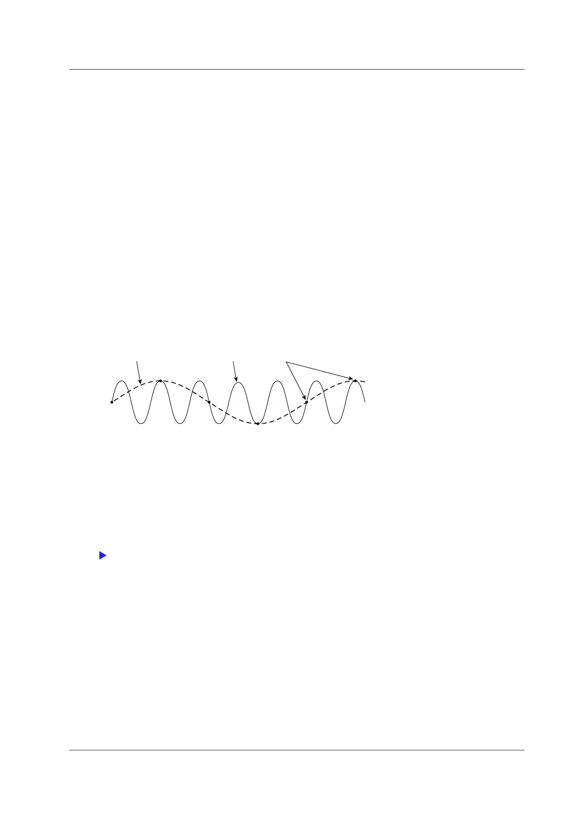
When an FFT is taken through the performance of A/D conversion on a repetitive waveform, a phenomenon
occurs in which frequency components that exceed half the frequency of the sampling frequency are detected as
low frequency components. This phenomenon is called aliasing.
Aliased signal Input signal Sampled points
Aliasing causes problems such as increased errors in measured values and incorrect measurements of the
phase angles on each harmonic. An anti-aliasing filter is used to prevent aliasing and eliminate high frequency
components that are irrelevant to the harmonic measurement.
For example, when an input signal with a fundamental frequency of 50 Hz is measured up to the 50th
order, the frequency of the 50th order is 2.5 kHz. Thus, a 5-kHz anti-aliasing filter is used to eliminate high
frequency components that are greater than or equal to approximately 5 kHz, which are irrelevant to harmonic
measurement.
This instrument uses the line filter as an anti-aliasing filter for harmonic measurements. For information about
how to configure the filter, see “Line Filter (Line Filter).”
The accuracy and the upper limit of the measurement bandwidth change when the anti-aliasing filter (line filter)
is turned ON. For details, see sections 6.15 and 6.16 in the Getting Started Guide, IM WT5000−03EN.
7 Harmonic Measurement Conditions

 Loading...


