14
IM 01B08B02-01EN
Basic Operations
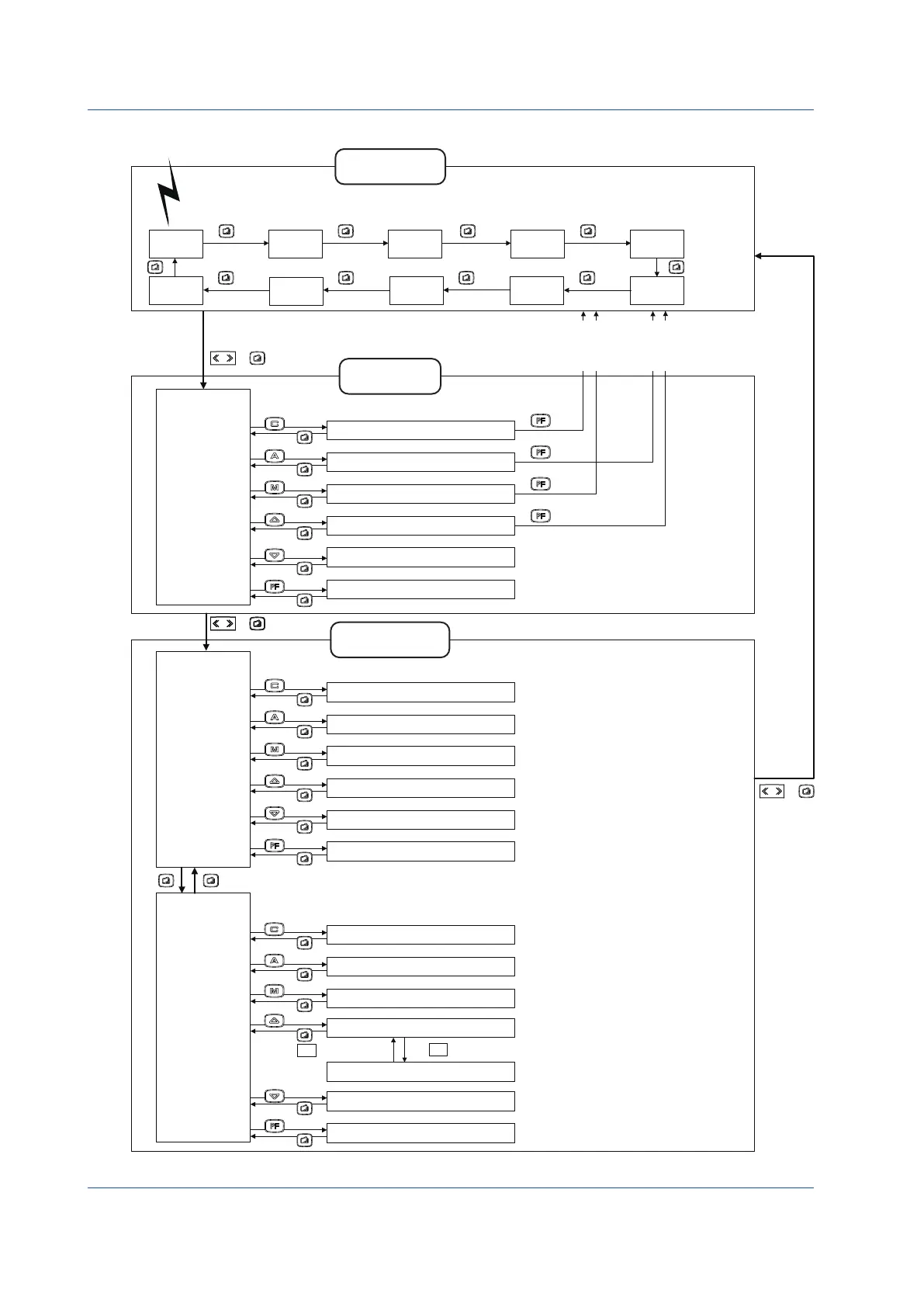
Display Switching in the Cascade or Selector Mode
□
PID1
STC1
OPE
OPE
OPE
OPE
PARAMETER
STC2
I/O DATA
CONFIG1
CONFIG2
CONFIG3
SC MAINT
PASSWORD
SMPL
DISPLAY
LCD
COMM
DI/DO
PID2
□
+
+
+
To the LOOP2, TREND2, METER2,
or DUAL 2 Display (To an Operation
Display on which the Tuning Menu
Display is selected for the first time)
To the LOOP1, TREND1, METER1,
or DUAL 1 Display (To an Operation
Display on which the Tuning Menu
Display is selected for the first time)
Operation Display
group
LOOP1
Display
LOOP2
Display
METER1
Display
METER2
Display
TREND1
Display
TREND2
Display
TREND3
Display
ALARM
Display
DUAL1
Display
DUAL2
Display
Tuning Display
group
Tuning Menu
Display
PID Setting Display 1
STC Setting Display 1
PID Setting Display 2
STC Setting Display 2
Parameter Setting Display
Input and Output Data Display
[PID1]
[PID2]
[STC1]
[STC2]
[PARAMETER]
[I/O DATA]
SHIFT
SHIFT
Press at the first line and at the last line.
↑
↓
Engineering
Menu Display 2
Setting Display for Operation Display
LCD Setting Display
Communication Setting Display
DI/DO Setting Display 1/2
DI/DO Setting Display 2/2
[DISPLAY]
[LCD]
[COMM]
[DI/DO]
Engineering Display
group
Engineering
Menu Display 1
Function Setting Display 1
Function Setting Display 2
Function Setting Display 3
Input Specification Setting Display
Password Setting Display
Sample Setting Display
[CONFIG1]
[CONFIG2]
[CONFIG3]
[SC MAINT]
[PASSWORD]
[SMPL]
FX TABLE
FX Table Setting Display
[FX TABLE]
SHIFT
0404E.ai
► Settings and description: YS1500 Indicating Controller/
YS1700 Programmable Indicating Controller User’s Manual
The turning ON/OFF of each Operation Display and the initial
Operation Display which appears when the power is turned
on can be set.
LCD MAINT
LCD Maintenance Display
[LCD MAINT]
* Not displayed in Selector mode.
Figure 4.4

 Loading...


