16
IM 01B08B02-01EN
16
Monitoring and Control of Regular Operations
(Operation Display)
Monitoring and Operating the Operation Display
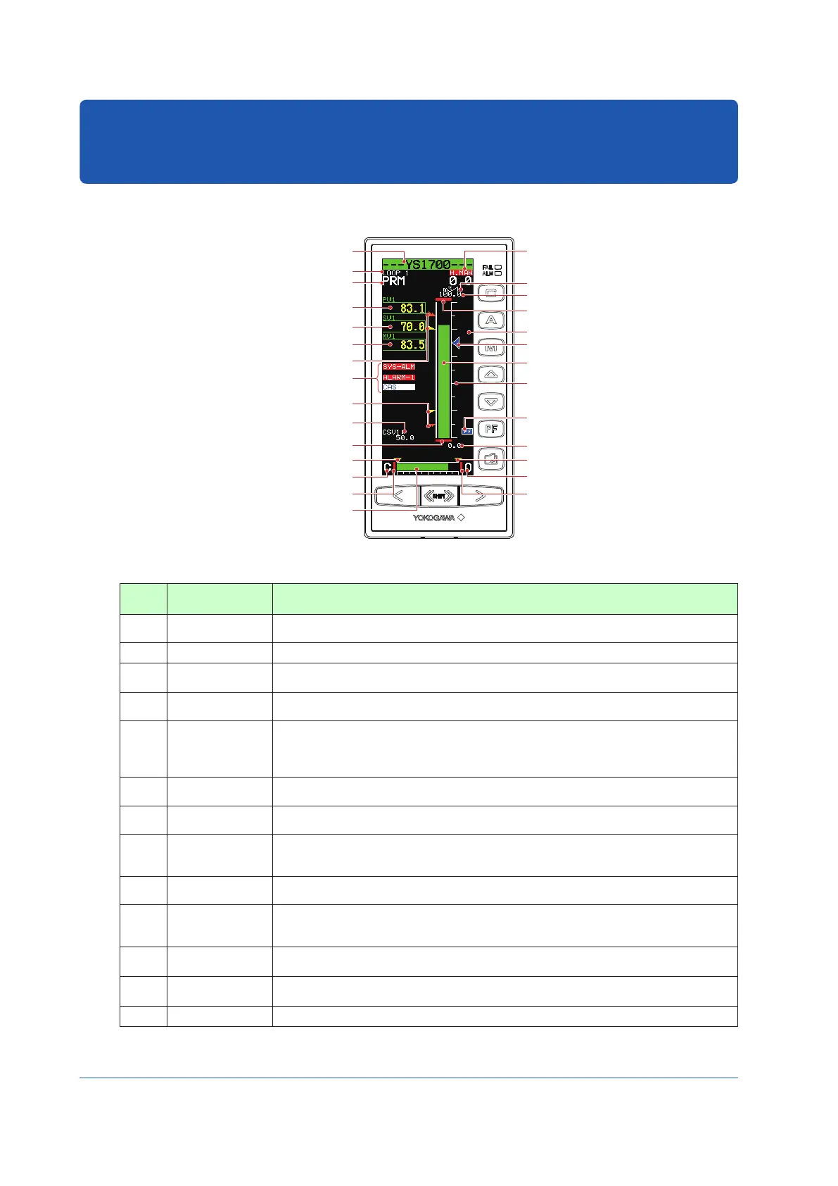
Monitoring and Operating the LOOP Display
Tag number (1)
Display title (2)
P-register display (18)
PV digital display (3)
SV digital display (7)
MV digital display (9)
HH pointer, PH pointer (5)
LL pointer, PL pointer (5)
Alarm generation display,
(17)
control status display
Cascade setting input value (20)
PV underflow (6)
ML pointer (11)
MV valve direction (13)
MV underflow (12)
(19) Operation status display
(14) Engineering units
(16) 100% value of scale
(6) PV overflow
(22) Key LOCK status display
(15) PV bar scale
(8) SV pointer
(4) PV bar
(21) PF key function display
(16) 0% value of scale
(11) MH pointer
(13) MV valve direction
(12) MV overflow
MV bar, MV scale (10)
Figure 5.1
Table 5.1
No. in
Figure
Name Description
(1) Tag number
A tag number combining alphanumeric characters and symbols having a maximum of 12 digits
is displayed on a loop basis.
(2) Display title The title of the display being shown is indicated.
(3) PV digital display
A PV value is displayed in engineering units in a digital value of five significant digits (seven
digits including a sign and decimal point).
(4) PV bar
A PV value is displayed in a bar. The bar display is in 200 dots at full scale (100%) and
increases/decreases on a dot (0.5%) basis.
(5)
PH, PL, HH, and LL
pointers
PH values (high limit alarm setpoints for PV) and PL values (low limit alarm setpoints for PV) are indicated
with triangular pointers, while HH values (high-high limit alarm setpoints for PV) and LL values (low-low
limit alarm setpoints for PV) are indicated with pointers which are overlapped pairs of triangles. Pointers
are clipped and displayed at 0% if PV values are below 0%, or displayed at 100% if they exceed 100%.
(6)
PV underflow and
PV overflow
A PV underflow is displayed if a PV value is below 0%, while a PV overflow is displayed if it
exceeds 100%.
(7) SV digital display
An SV value is displayed in engineering units in a digital value of five significant digits (seven
digits including a sign and decimal point).
(8) SV pointer
SV values are indicated with triangular pointers. The pointer display moves up and down with
a resolution of 0.5%. Pointers are clipped and displayed at 0% if SV values are below 0%, or
displayed at 100% if they exceed 100%.
(9) MV digital display
An MV value is displayed in a digital value of four significant digits (six digits including a sign
and decimal point, with the number of decimal places fixed to one digit) in a % display.
(10)
MV bar
MV scale
An MV value is displayed in a bar. The bar display is in 80 dots (100%) at full scale, divided into
20 blocks (5%) for display. It increases/decreases on a dot (1.25%) basis. A scale divided into
10 (10% segments) is also displayed.
(11) MH and ML pointers
MH values (high limit setpoints of MV) and ML values (low limit setpoints of MV) are indicated
with triangular pointers.
(12)
MV underflow and
MV overflow
An MV underflow is displayed if an MV value is below 0%, while an MV overflow is displayed if it
exceeds 100%.
(13) MV valve direction MV valve direction is displayed as [C] (closed) or [O] (open). The valve direction can be set.

 Loading...