9
IM 01B08B02-01EN
Part Names
Part Names
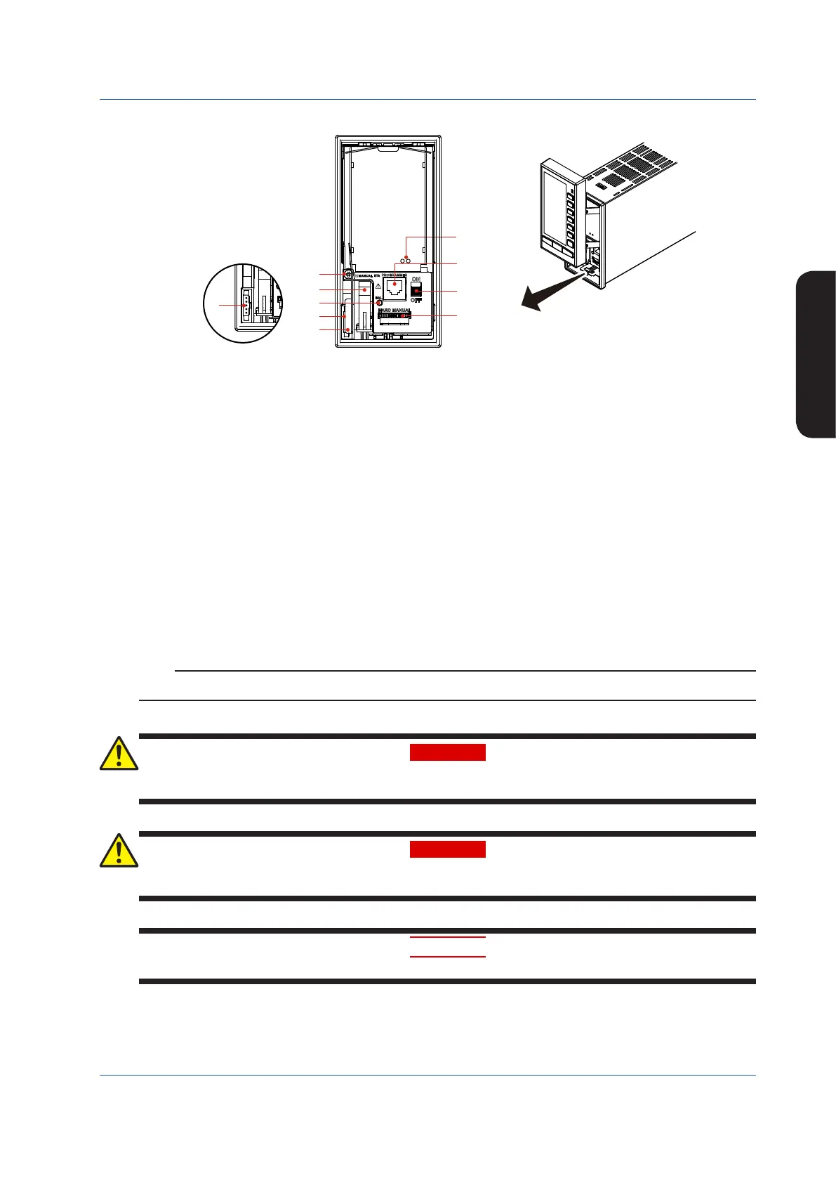
Part Names of the Internal Panel Seen with the Front Panel Swung up
(1)
(9)
(7)
(5)
(8)
(4)
(6)
(2)
(3)
(3)
Figure 2.5
(1) Connector for connection to a PC (PROGRAMMER)
This is a communication cable connector for downloading, uploading, or monitoring parameters or user programs set using
the YSS1000 Setting Software.
► YSS1000:YSS1000SettingSoftware/YS1700ProgrammableFunctionUser’sManual
(2) Metal lever
Touch the metal lever to discharge static electricity. Before you connect the cable to the YS110 connector, touch the metal
lever.
(3) Connector for YS110 standby manual station (MANUAL STA)
(4) Internal unit release lever
(5) Hard manual operation wheel (HARD MANUAL)
An operation wheel to manipulate an output
(6) MV balance lamp (BAL) (Color: green)
Lights up when a manipulated output variable and the hard manual unit’s output value agree with each other.
(7) Hard manual selector switch (ON/OFF)
The switch used to switch to a manipulated variable (MV) set using the hard manual operation wheel.
(8) An internal unit fixing screw
(9) LED and switch for repair
Contact us for repair.
► Regardingitems(2),(3),(5),(6),and(7)above:see“BackupOperationintheEventofInstrumentFailure”inthismanual.
Note
For products with suffix code -2xx, there are no hard manual unit-related parts ((5), (6), and (7)).
WARNING
Do not remove the internal unit from the instrument case. Contact YOKOGAWA’s sales office or sales representative when
removing the internal unit, as safety standard inspection is required.
WARNING
Explosionhazard.
Do not remove or insert the internal unit in explosive atmospheres.
CAUTION
Products with optional code /FM or /CSA cannot satisfy the explosion protection standards if the internal unit is removed.

 Loading...