28
IM 01B08B02-01EN
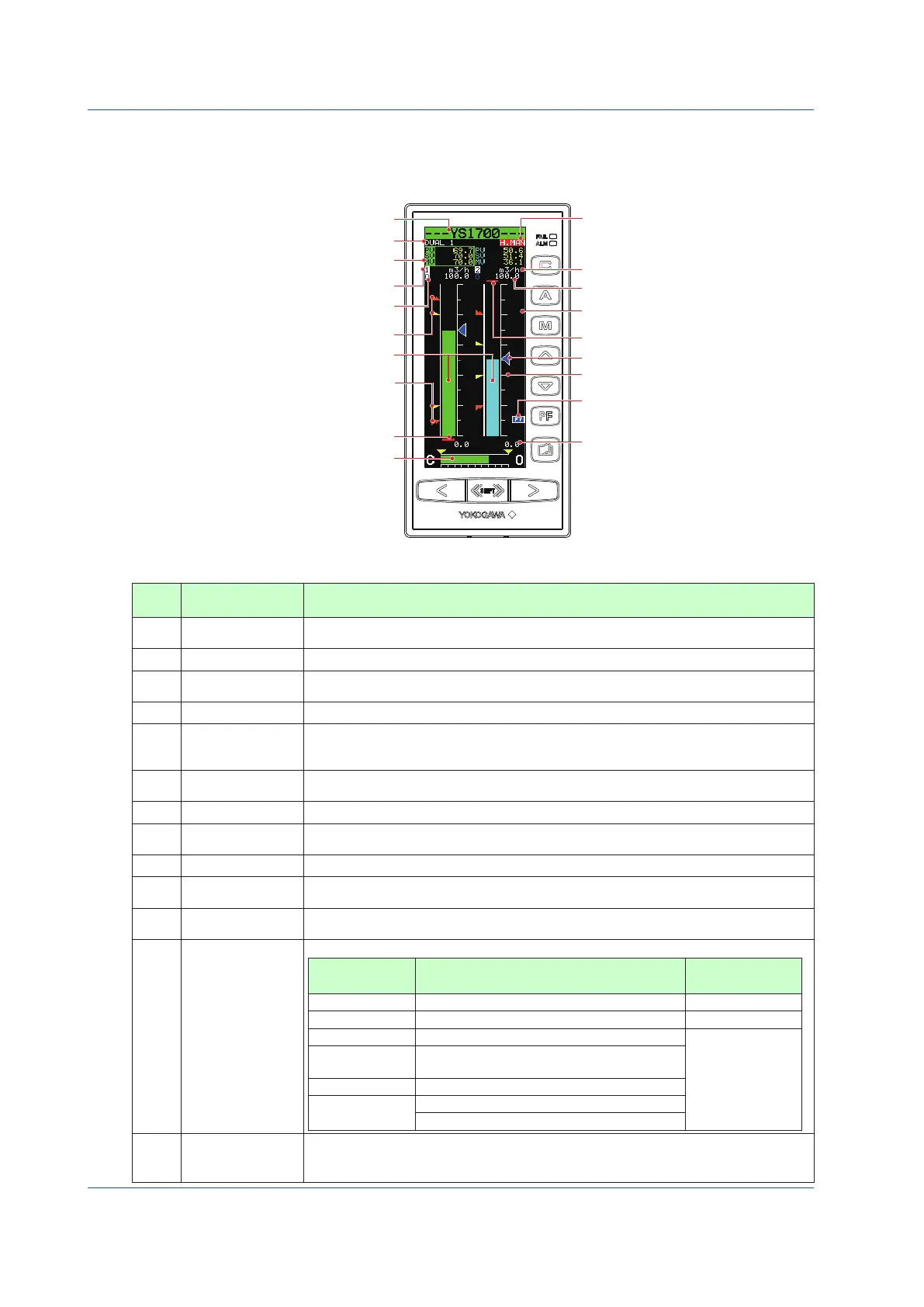
Monitoring and Control of Regular Operations (Operation Display)
Monitoring and Operating the DUAL Display
The DUAL Display has two display titles: DUAL1 and DUAL2.
Information concerning PV, SV, and MV are displayed simultaneously for both loops. The loop 1 information is shown on the left,
and the loop 2 information is displayed on the right.
HH pointer, PH pointer (13)
LL pointer, PL pointer (13)
PV bar (6)
PV undreflow (11)
MV display (14)
Tag number (1)
Display title (2)
PV, SV, MV digital display
(3)
(Inverse display: Operable loop)
(7) Engineering units
(8) 100% value of scale
(11) PV overflow
Loop number (4)
Control substatus (5)
(12) Operation status display
(16) Key LOCK status display
(10) SV pointer
(9) PV bar scale
(15) PF key function display
(8) 0% value of scale
Figure 5.6
Table 5.15
No. in
Figure
Name Description
(1) Tag number
The tag number of the loop 1 appears for DUAL1 Display, while that of the loop 2 appears for
DUAL2 Display.
(2) Display title The title of the display being shown is indicated.
(3)
PV, SV, and MV
digital display
PV, SV, and MV digital values of the loop 1 are displayed at the left and those of the loop 2 at
the right. The loop that is inverse displayed can be operated.
(4) Loop number Loop numbers “1” (left) and “2” (right) are displayed.
(5) Control substatus
Control substatus is inverse displayed in one character below the loop number. The substatus
display shown in Table 5.17 is indicated depending on controller mode in the multi-function mode or
a control module in the programmable mode. Nothing is indicated in cases other than this.
(6) PV bar
PV1 (left) and PV2 (right) are displayed in bars. The bar display is in 200 dots at full scale
(100%) and increases or decreases on a dot (0.5%) basis.
(7) Engineering units
Engineering unit 1 (left) and engineering unit 2 (right) are displayed in a maximum of seven digits.
(8)
0% value of scale,
100% value of scale
SCL1, SCH1 (left), SCL2, and SCH2 (right) are displayed in engineering units in digital values
of five significant digits (seven digits including a sign and decimal point).
(9) PV bar scale The PV bar scale is displayed divided into a maximum of 10 divisions (10% segments).
(10) SV pointer
SV1 (left) and SV2 (right) are indicated with triangular pointers. The pointer display moves up
and down with a resolution of 0.5%.
(11)
PV underflow,
PV overflow
PV underflow (PV1 at the left, PV2 at the right) is displayed if a PV value is below 0%, while PV
overflow (PV1 at the left, PV2 at the right) is displayed if it exceeds 100%.
(12)
Operation status
display
The controller operation status is displayed.
Display Description
Display
Priority Order
[POWER DOWN] Power down is being detected. (1)
[H.MAN] Hard manual selector switch has been activated. (2)
(No indication) The instrument is operating.
(3)
[STOP] Operation stopped (such as while setting a
function on the Engineering Display, etc.)
[TEST1]
Test run mode 1 (only in the programmable mode)
[TEST2]
Test run mode 2 (only in the programmable mode)
Simulation program is being executed
(13)
PH, PL, HH, and LL
pointers
PH values (high limit alarm setpoints for PV) and PL values (low limit alarm setpoints for PV) are indicated
with triangular pointers, while HH values (high-high limit alarm setpoints for PV) and LL values (low-low
limit alarm setpoints for PV) are indicated with pointers which are overlapped pairs of triangles.

 Loading...