25
IM 01B08B02-01EN
Monitoring and Control of
Regular Operations
Monitoring and Control of Regular Operations (Operation Display)
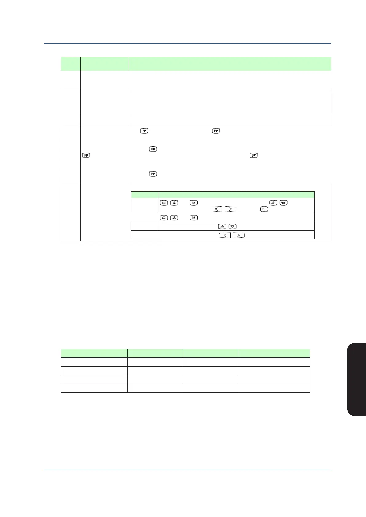
Table 5.12
No. in
Figure
Name Description
(10)
Time span scale
The time span scale (a vertical line) is displayed by a dotted line at the 60-line positions. If the
scale marks are divided into 4 divisions or more, the time span scale is also displayed at the
30-line positions.
(11)
Trend display time
span
The trend display time span setpoint is displayed. The trend display span is 90 lines, but it
represents the time span for 60 lines. Trend display is provided such that the 0-line position
is the current time, while the 90-line position is the maximum past time. Changing the trend
display time span causes data that has been displayed up to that time to be cleared.
(12)
MV display
The MV bar, MV scale, MH pointer, ML pointer, MV underflow, MV overflow, and MV valve
direction are displayed. The display contents are the same as those of the LOOP Display.
(13)
key function display
The key function is displayed. The key function display is different in the multi-function
mode and the programmable mode.
1) Multi-function mode
The key function is set using the PF key function selection parameter [PFKEY].
When the STC mode selection is “not OFF” and the “ key has been set to STC”, the
function display becomes [STC]. In other cases, nothing is displayed.
2) Programmable mode
The key function can be defined in user programs.
The function display becomes [PF] in the programmable mode.
(14)
Key LOCK status display
The key LOCK status is displayed.
Display Description
[ALLK]
, , and keys, SV increase and decrease ( , ) keys, MV
increase and decrease ( , ) keys, and key are disabled.
[MDLK]
, , and keys are disabled.
[SVLK]
SV increase and decrease (
, ) keys are disabled.
[MVLK]
MV increase and decrease (
, ) keys are disabled.
Operating the TREND Displays
The following operations can be conducted on the TREND 1 and TREND 2 Displays:
(1) Operation mode switching of the loop displayed
(2) SV setting operation of the loop displayed
(3) MV operation of the loop displayed
(4) PF key operation
The following operations can be conducted on the TREND 3 Display:
(1) MV1 operation
(2) PF key operation
The operation methods are the same as those of the LOOP Display.
The following table shows the contents displayed in trend data 1 to 4.
TREND 1 Display TREND 2 Display TREND 3 Display
Trend data 1
PV1 PV2
Set using the TRDS1 parameter
Trend data 2
SV1 SV2
Set using the TRDS2 parameter
Trend data 3
MV1 (Note) MV2 (Note)
Set using the TRDS3 parameter
Trend data 4 None None Set using the TRDS4 parameter
Note: When the controller mode is set to the cascade/selector mode, MV will be displayed.

 Loading...


