JOHNSON CONTROLS
9
FORM 160.84-N1
ISSUE DATE: 11/22/2016
1
SECTION 1 - OVERVIEW
GENERAL
This manual provides instructions for rigging and in-
stalling a YMC
2
Liquid Chilling Unit.
Chillers can be shipped as a single factory assembled,
piped, wired package, requiring a minimum of field la-
bor to make chilled water connections, condenser wa-
ter connections, refrigerant atmospheric relief connec-
tions, and electrical power connections. (Refrigerant
charges shipped separately unless optional condenser
isolation valves are ordered.)
They can also be shipped dismantled when required by
rigging conditions, but it is generally more economical
to enlarge access openings to accommodate the factory
assembled unit. Chillers that are shipped dismantled
MUST be field-assembled under the supervision of a
Johnson Controls representative, but otherwise instal-
lation will be as described in this manual.
COMPONENT COMBINATIONS
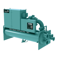
Figure 1 identifies the major components of the YMC
2
Chiller. The chiller is customized based on the selected
combination of Motor, Compressor, Evaporator, and
Condenser. Section 5 - Dimensions, Nozzle Arrange-
ments And Weights lists all of the allowable YMC
2
Chiller combinations.
FIGURE 1 - YMC
2
CHILLER COMPONENTS
LD14022b
COMPRESSORTRANSFORMERS
OPTIVIEW
CONTROL
PANEL
CONDENSER
EVAPORATOR
VSD
COOLING
PIPING
COMPACT
WATERBOXES
VARIABLE
SPEED
DRIVE
DIRECT-DRIVE
MOTOR
MAGNETIC
BEARING
CONTROLLER
LIFTING
OPENINGS
POWER
PANEL

 Loading...