Unit Installation
The first step in the installation of your processor is to disconnect the negative terminal of the battery
to prevent damage to the equipment and to the car's electrical system. The HDSP-V processor needs to
be securely mounted in a location where it will not be exposed to excessive heat, moisture, or vibration.
When choosing a location be sure there is room for all the cables and wiring that will be connected to
HDSP-V and be sure you have easy access to the USB control input to connect to the PC. If you are
using the factory high level inputs from an OEM amplifier you will need to bring those connections to
the location as well. You will also want to run the cable for your dash remote, leaving plenty of extra
cable at the front until you pick a permanent location for the dash remote.
12 Volt Connections
• The
+12V Battery
wire should have a 2A fuse mounted in-line within 18 inches of the battery. If you
are connecting to a distribution block there should be a 2A fuse in-line at that connection.
• The
+12V Key
(Acc) power wire allows the HDSP to be turned when the Key is in Acc or Run positions.
• The
Ground
connection is critical to the performance of the processor. Inadequate or loose ground
connections can not only damage the processor, but they open a path for many sources of unwanted
noise. Make sure you have a good solid ground point to bare metal which is connected to the car frame.
• The
+12-Volt In for Turn-On
connects to the turn-on wire from the head unit. All aftermarket units and
many factory OEM units have these turn-on trigger wires. When available you should always use them.
•
Auto-on Sensing
: Many of the newer cars however do not have turn-on wires in the factory harness.
For these systems there is an auto-on from Audio Input switch in the GUI that activates sensors that
read signal from the speaker input wires and turn on the HDSP automatically when the factory system
is turned on.
• The
+12-Volt Output
connection is used to provide turn-on current for your amplifiers. This connection
will be active whether you use the +12 turn-on from the head unit, or you use the Auto-on system. All
amplifiers should use this source for the turn-on so the Processor can control the turn-on of the amplifiers.
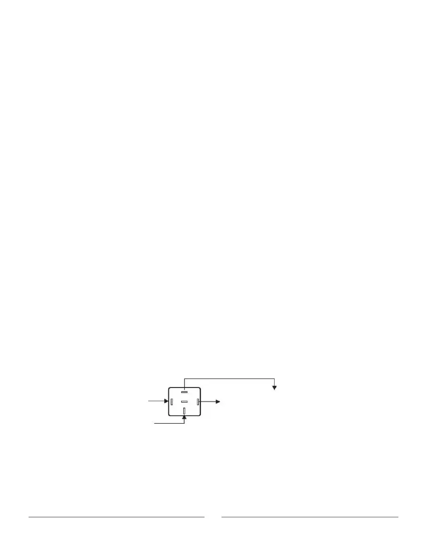
NOTE: To avoid turn-on pops and other noises all amplifiers must use the turn-on output of the HDSP for their trigger
inputs. For multiple amplifiers turn on, it is safest to use a relay as below (common Bosch Style Automotive Relay).
After the +12 Volt and Ground connections are completed you can finalize all the other connections
at the HDSP except the RCA signal cables to the amplifiers. These should not be connected to the
HDSP until after the input levels and default crossovers are set. This will avoid damage to the speakers
during gain setting.
From DSP turn-on output
From Car Battery
To all amplifiers turn-on wires
To Ground
13
 Loading...