Pagina 9
pinpin
pinpin
pin
functionfunction
functionfunction
function
descriptiondescription
descriptiondescription
description
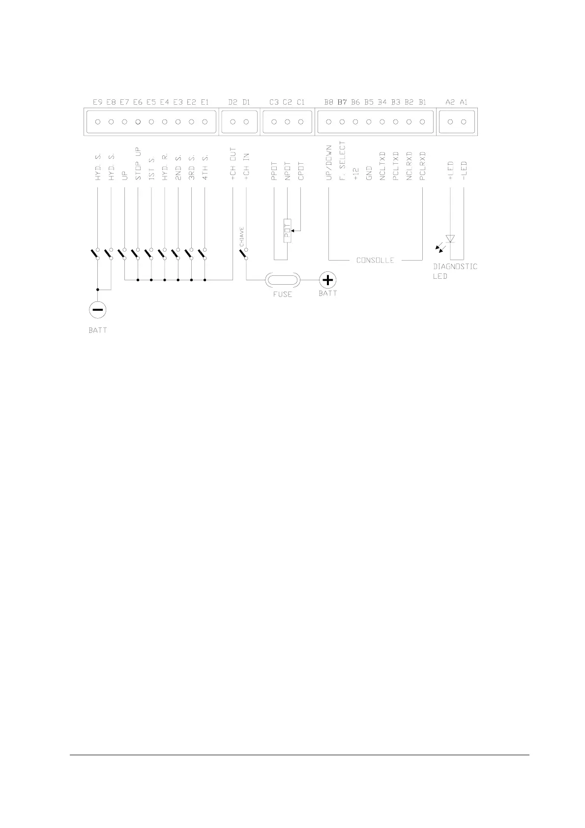
A1 -LED Alarm LED negative: to be connected to the cathode
A2 +LED Alarm LED positive: to be connected to the anode
Output current 12mA, for standard type LED
B1 PCLRXD Serial reception positive
B2 NCLRXD Serial reception negative
B3 PCLTXD Serial transmission positive
B4 NCLTXD Serial transmission negative
B5 GND Console supply negative
B6 +12 Console supply positive
B7 FUNCTION SELECT Channel for mini-console (speed signal)
B8 UP/DOWN Channel for mini-console (speed ref.)
C1 CPOT Potentiometer central unit: connected to the potentiometer
cursor. For speed regulation, the useful signal ranges
from 0 Volt (minimum speed) to 10 V (maximum speed).
C2 NPOT Potentiometer negative: a battery negative.
C3 PPOT Potentiometer positive: a 12 V output.
Do not short circuit this terminal toward the battery negative
or apply a resistive load of less than 500 ohm.
D1 +CH IN To be connected to the key.
D2 +CH OUT The positive to be sent to the function request microswitches
is taken from this pin. This positive is taken after the
internal diode.
3.4 LOGIC BOARD CONNECTORS3.4 LOGIC BOARD CONNECTORS
3.4 LOGIC BOARD CONNECTORS3.4 LOGIC BOARD CONNECTORS
3.4 LOGIC BOARD CONNECTORS