Installation of hardware components
000000-1865-713-GA-en-US-080622
Installation of hardware
components
WARNING – GENERAL HAZARDS
The device may not be stored or operated in ambient conditions other
than those prescribed (see Technical data section on page 31 and
following).
CAUTION – GENERAL HAZARDS
When mounting the Option Reference Image ensure that you do not trap
your fingers between the device and the spring holder.
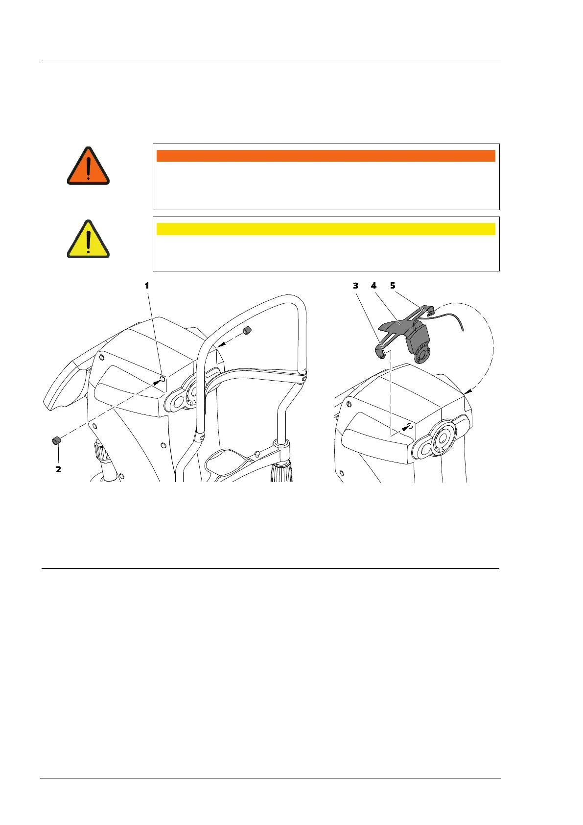
• Insert the two sleeves (2, Fig. 4) into the two upper drill holes (1, Fig. 4)
on the right and left side of the IOLMaster 500 facing the patient.
• First insert the pin (3 or 5, Fig. 4) into the sleeve on one side of the
holder.
• Carefully pull the holder (4, Fig. 4) apart and put the second pin
(3 or 5, Fig. 4) of the holder into the sleeve on the other side of the
IOLMaster 500 so that it clicks into place.
1
Drill hole
2
Sleeve
3
Left pin of holder
4
Holder
5
Right pin of holder
4 Mounting the holder


 To Next Page