

J
Jennifer SmallJul 30, 2025
Why won't my Zenith DVD VCR Combo copy the disc?
- JJennifer SimpsonJul 30, 2025
If your Zenith DVD VCR Combo won't copy a disc, it might be because the DVD is copy-protected. Try using a disc that is not copy-protected.
Why won't my Zenith DVD VCR Combo copy the disc?
If your Zenith DVD VCR Combo won't copy a disc, it might be because the DVD is copy-protected. Try using a disc that is not copy-protected.
What to do if my Zenith ZRY-316 recording is not completing?
Your Zenith DVD VCR Combo might not be recording because the disc is damaged. The solution is to replace the damaged disc.
What to do if I can't set a timer program on my Zenith ZRY-316?
If you can't enter a timer program on your Zenith DVD VCR Combo, it may be because there are already 8 timer programs set. Delete some timer programs to set a new one.
Why can't I enter a timer program on my Zenith DVD VCR Combo?
If you cannot enter a timer program on your Zenith DVD VCR Combo, it is possible that a recording is already in progress. Wait until the current recording is finished.
What to do if my Zenith ZRY-316 says 'disc full'?
If your Zenith DVD VCR Combo won't record, it might be full. If there are already 99 titles (DVD-RW, DVD-R) or 49 titles (DVD+RW, DVD+R) recorded on the disc, delete some titles to free up space.
Guidelines for trained technicians, emphasizing original design adherence and safety components.
Explanation of symbols used in service literature to denote safety information.
Instructions for servicing, including isolation transformer use and post-service checks.
Detailed steps to prevent fire and shock hazards during servicing.
Recommendations for safe and proper installation of video products.
Essential safety measures before and during servicing of VCR+DVD RECODER.
Procedure to check insulation resistance between attachment plug and chassis.
Techniques to reduce component damage caused by static electricity.
Instructions on how to burn discs for updating DVD and Loader programs.
Step-by-step guide for DVD upgrade format number 1.
Step-by-step guide for DVD upgrade format number 2.
Technical details for power, dimensions, mass, temperature, and humidity.
Details on recording formats, recordable discs, and recording time.
Information on sampling frequency and compression format for video recording.
Technical details for VCR head system, tape speed, and channel specifications.
Technical details for DVD laser system, frequency response, and signal-to-noise ratio.
List of input and output terminals and their specifications.
Requirements for playing MP3, WMA, and JPEG discs.
Exploded view of the unit's cabinet and main frame.
Exploded view of the RL-05 loader deck mechanism.
Exploded view of the packing accessories included with the product.
Diagram showing the overall wiring connections of the unit.
Procedures for adjusting the VCR electrical system.
Guide for troubleshooting VCR electrical issues.
Block diagrams illustrating the VCR electrical system.
Detailed circuit diagrams for the VCR system.
Layouts of the VCR printed circuit boards.
Guide for troubleshooting VDR electrical issues.
Block diagrams illustrating the VDR electrical system.
Detailed circuit diagrams for the VDR system.
Layouts of the VDR printed circuit boards.
Block diagram of the Power Supply (SMPS) circuit.
Block diagram of the AVCP circuit for PB and REC modes.
Block diagram illustrating the system control.
Block diagram showing audio/video jack connections.
Block diagram for the tuner and MTZ circuits.
Block diagrams for AVCP circuit in EE, PB, and REC modes.
Detailed circuit diagram for the Power Supply (SMPS) section.
Detailed circuit diagram for the tuner section.
Detailed circuit diagram for the Audio/Video sections.
Detailed circuit diagram for the Hi-Fi audio section.
Detailed circuit diagram for the system control.
Detailed circuit diagram for the audio/video jack connections.
Circuit diagram for the timer function with 2 tools.
Circuit diagram for the timer function with 3 and 8 tools.
Circuit diagram for the timer function with 4 tools.
Circuit diagram for the timer function with 6 tools.
Circuit diagram for the timer function with 7 tools.
Oscilloscope waveforms for IC301 signals in PB mode.
Photographs of IC501 waveforms in REC/PB mode.
Printed circuit board layout for the VCR main board.
Printed circuit board layout for the SMPS (Power Supply) module.
Printed circuit board layout for the input/output jack section.
Printed circuit board layout for the key input section.
Printed circuit board layout for the timer control section.
Troubleshooting steps for VDR power supply issues.
Troubleshooting steps for various VDR power supply voltages.
Troubleshooting steps for missing component video signals.
Troubleshooting for missing composite or S-Video signals.
Troubleshooting steps for no TV or external input video signals.
Troubleshooting steps for missing audio output in various modes.
Troubleshooting for missing external audio inputs.
Overall block diagram of the system architecture.
Internal block diagram of the MPEG encoder IC.
Internal block diagram of the MPEG decoder IC.
Internal block diagram of the digital video decoder IC.
Block diagram of video input and record paths.
Block diagram of analog and digital video inputs.
Block diagram of analog and digital audio inputs.
Circuit diagram for the MPEG encoder IC.
Circuit diagram for the MPEG decoder IC.
Circuit diagram for video connectors.
Circuit diagram for audio ADC and DAC interface.
Circuit diagram for the DV (Digital Video) section.
Photographs of IC501 waveforms for various signals.
Printed circuit board layout of the VDR main board (top view).
Printed circuit board layout of the VDR main board (bottom view).
Identification of deck mechanism parts with top and bottom views.
Procedures for disassembling and assembling the deck mechanism.
Procedures for adjusting the deck mechanism components.
Maintenance and checks for video function protection.
Troubleshooting guide for deck mechanism issues.
Troubleshooting guide for front loading mechanism problems.
Exploded diagrams of the VCR mechanism sections.
Troubleshooting steps for various deck mechanism failures.
Troubleshooting steps for front loading mechanism loading issues.
Guide for troubleshooting electrical issues in the RL-05 loader.
Illustrations of key waveforms for loader operation.
Comparison of DVD-R/RW, DVD+R/RW, and DVD-ROM disc structures.
Instructions for using test tools for measurement and adjustment.
Block diagrams illustrating loader components and signals.
Detailed circuit diagrams for loader sections.
Chart detailing voltage measurements for various circuit components.
Layouts of the loader main printed circuit boards.
Troubleshooting steps for abnormal tray operation.
Troubleshooting steps for abnormal sled motor operation.
Troubleshooting steps for abnormal spindle motor operation.
Troubleshooting steps for unstable focus servo.
Troubleshooting steps for abnormal focus actuator operation.
Troubleshooting steps for unstable track servo.
Troubleshooting for CD-ROM recognition failure.
Troubleshooting for DVD recognition failure.
Troubleshooting for DVD±R/RW recognition failure.
Procedure for checking laser operation when abnormal.
Troubleshooting steps for writing failures.
Procedure for checking the writing part of the disc drive.
Waveforms for power and reset signals.
Waveform for the main clock signal of IC202.
Waveform for the SDRAM clock signal.
Waveforms for tray open/close signal 1.
Waveforms for tray open/close signal 2.
Waveforms for sled move signal 1.
Waveforms for sled move signal 2.
Waveforms related to focus search signals.
Waveform for the laser turn on signal.
Waveforms for judging CD disc types.
Waveforms for judging CD and CD-R disc types.
Waveforms for judging CD-RW disc types.
Waveforms for judging DVD disc types.
Waveforms for judging DVD_SINGLE&R disc types.
Waveforms for judging DVD_DUAL disc types.
Waveforms for judging DVDRW disc types.
Waveforms for the spindle motor operation (Part 1).
Waveforms for the spindle motor operation (Part 2).
Waveforms for focus signal during CD operation.
Additional waveforms for focus signal during CD operation.
Waveforms for focus signal during DVD operation.
Additional waveforms for focus signal during DVD operation.
Waveforms for track off signal during CD operation.
Waveforms for track off signal during DVD operation.
Waveforms for tilt driver signal during disc reading.
RF waveforms captured during DVD playback.
RF waveforms captured during CD playback.
Waveforms for wobble signal during DVD-R/RW reading.
Waveforms for wobble signal during DVD+R/RW reading/writing.
Waveforms for LD enable signal during DVD operation.
Waveforms for LD enable signal during CD operation.
Waveforms for laser power during DVD+RW reading.
Waveforms for laser power during DVD+RW erase.
Waveforms for laser power during writing (initial state).
Waveforms for laser power during writing (processing).
Comparison of recording layers in DVD discs.
Specifications table comparing different DVD disc types.
Description of materials used in DVD discs.
Layout of drive areas, lead-in, and lead-out zones on discs.
Block diagram and operation of the ALPC circuit.
Configuration of the ALPC measurement system.
Details on the ALPC program files and settings.
Instructions on how to run the ALPC program software.
Procedures for performing LD tests on CD and DVD modes.
Procedure for setting optical power for DVD and CD.
Checking optical power settings against recorded parameters.
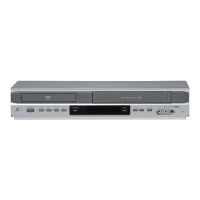
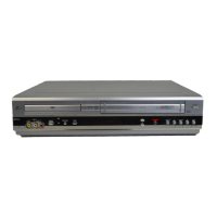
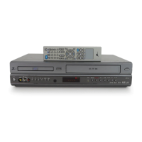
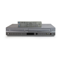
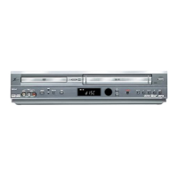
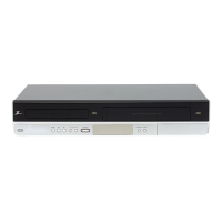
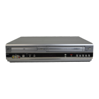
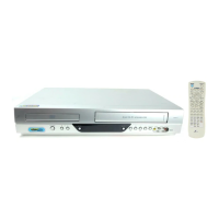
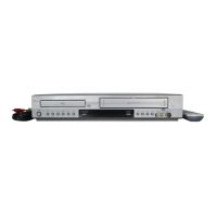
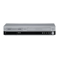
| Brand | Zenith |
|---|---|
| Model | ZRY-316 |
| Type | DVD VCR Combo |
| DVD Player | Yes |
| VCR Player | Yes |
| Number of VCR Heads | 4 |
| Video Output System | NTSC |
| Region Code | 1 |
| Remote Control | Yes |
| Playable Disk Types | DVD, CD |
| Audio Formats | Dolby Digital |
| Connectors | Composite Video |